Sign In
Upload
Manuals
Brands
Motorola Manuals
Radio
MTM700
Motorola MTM700 Manuals
Manuals and User Guides for Motorola MTM700. We have
3
Motorola MTM700 manuals available for free PDF download: Detailed Service Manual, Basic Service Manual, Specification
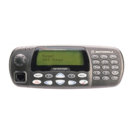
Motorola MTM700 Detailed Service Manual (328 pages)
TETRA Mobile Radio 380-430 MHz (MT912) 806-870 MHz (MT712)
Brand:
Motorola
| Category:
Radio
| Size: 13.57 MB
Table of Contents
Computer Software Copyrights
2
Trademarks
2
Document History
3
Compliance with RF Energy Exposure Standards
5
Transmit and Receive
6
Mobile Antennas
6
Fixed Site Antennas
7
Electromagnetic Interference/Compatibility
7
Facilities
7
Vehicles
7
Driver Safety
8
Operational Warnings
8
For Vehicles with an Air Bag
8
Potentially Explosive Atmospheres
8
Blasting Caps and Areas
8
Additional Important Information
9
For Servicing and Installing the Radio
9
Table of Contents
11
Chapter 1 Scope & Warranty Information
21
Scope of this Manual
21
Manuals & User Guides
22
Warranty and Service Support
23
After Warranty Period
23
Chapter 2 Model Information & Accessories
25
MTM700 Mobile Radio Model Information
25
Sales Model Nomenclature
25
MTM700 Model Specifications
26
MTM700 Model Descriptions
27
MTM700 Accessories-To-Model Chart
27
Chapter 3 Overview
31
Chapter 4 Theory of Operation
33
Block Diagram and Overview
35
Receiver Section
36
Transmitter Section
37
Controller Section
38
Frequency Generating Section
39
Theory of Operation (400 Mhz)
35
Block Diagrams Descriptions
39
Receiver Path
39
Transmitter Path
40
Frequency Generating Section
41
Main Synthesizer
42
Transmit Frequency Translation Loop
42
Controller Section
43
Detailed Circuit Description
44
Receiver Path, Detailed Circuit Description
44
Antenna Switch
44
AGC_0 Attenuator
44
Pre Selector Filter
44
LNA and AGC_1 Attenuator
44
Second Pre-Selector
44
Mixer
45
IF Filter, Amplifier, AGC_2 Attenuator
45
IF Digitizing Subsystem
45
Transmitter Path, Detailed Circuit Description
46
Addag
46
Tx lo
46
Lnodct
46
RF Power Amplifier
47
Directional Coupler and RF Feedback Path
47
Antenna Switch
47
Harmonic Filter
47
Frequency Generating Section Detailed Circuit Description
48
Reference Oscillator - TCXO
48
Main VCO and Main Synthesizer
48
Transmit Frequency Translation Loop
49
Controller Section
50
DC Power Distribution
50
Microprocessor
53
Host Memories
54
Serial Peripheral Interface (SPI)
54
RS232, SB9600, SBEP Serial Interfaces
54
Radio Audio System
55
Diagram and Overview
57
Receiver Section
58
Transmitter Section
59
Controller Section
60
Frequency Generating Section
61
Theory of Operation (800 Mhz)
57
Block Diagrams Descriptions
61
Receiver Path
61
Transmitter Path
62
Frequency Generating Section
63
Main Synthesizer
64
Transmit Frequency Translation Loop
64
Controller Section
65
Detailed Circuit Description
66
Receiver Path, Detailed Circuit Description
66
Antenna Switch
66
Pre-Selector Filter
66
Lna
66
Second Pre-Selector
66
Mixer
66
IF Filter, Amplifier, Dynamic Range Extension
66
IF Digitizing Subsystem
67
Transmitter Path, Detailed Circuit Description
68
Addag
68
Tx lo
68
RF Power Amplifier
69
Directional Coupler and RF Feedback Path
69
Isolator
69
Antenna Switch
69
Harmonic Filter
69
Frequency Generating Section Detailed Circuit Description
70
Reference Oscillator - TCXO
70
Main VCO and Main Synthesizer
70
Transmit Frequency Translation Loop
71
Controller Section
72
DC Power Distribution
72
Microprocessor
75
Host Memories
76
Serial Peripheral Interface (SPI)
76
RS232, SB9600, SBEP Serial Interfaces
76
Radio Audio System
77
Standard Control Head
79
Power Supplies
79
Voltage Regulator Circuit
79
Power on / off
80
Microprocessor Circuit
80
SBEP Serial Interface
81
Keypad Keys
81
Status LED and Back Light Circuit
81
Liquid Crystal Display (LCD)
82
Microphone Connector Signals
82
Electrostatic Transient Protection
83
Theory of Operation (Control Heads)
79
Expansion Head
84
Overview
84
General
84
Circuit Description
84
Remote Mount Head
85
General
85
Description
85
Motorcycle Control Head
86
Power Supplies
86
Volume Control / ON/OFF Switch
86
Microcontroller (U4)
86
Crystal Oscillator
86
LCD Display
86
Backlight
86
Controller
87
Power Supplies
87
Temperature Sensor
87
Keypad
87
Backlight
87
External Microphones and Speakers
87
Helmet
87
Chapter 5 Programming the Radio
89
Codeplug Programming
91
Codeplug Reading
91
Frequency Programming
92
Application Programming
93
Chapter 6 Test Setup & Testing
95
Typical Test Setup
95
Before Testing
95
Test Equipment
96
Test Check List
97
Receiver Tests
98
Transmitter Tests
98
Call Processing Tests
98
Duplex Test
98
Configuration of the IFR 2968 System Setup
99
Configuration of the IFR 2968 Manual Test Screen
102
RF Tests
103
Receiver Tests
103
Simulate Base Station (Registration)
103
RSSI Test
103
Transmitter Tests
104
Call Processing Test
105
Talk Back
105
Call to Mobile
105
Duplex Test (Phone/Private Mode)
105
Digital Duplex Test (Tx)
105
Service Flow Chart (Board Level)
107
Self Check (Error & Fail Codes)
108
Fuses on the Mainboard
110
General
31
Digital Modulation Technique
31
Voice Compression Technology
31
Section Introduction
33
Programming of Software Features and Flashing of Radio Firmware
89
Chapter 7 Maintenance
111
Introduction
111
Preventive Maintenance
111
Inspection
111
Cleaning
111
Cleaning External Plastic Surfaces
112
Cleaning Internal Circuit Boards and Components
112
Safe Handling of CMOS and LDMOS Devices
113
Repair Procedures and Techniques - General
114
Parts Replacement and Substitution
114
Disassembling and Reassembling the Radio - General
114
Radio Disassembly and Reassembly - Detailed
115
Control Head Removal
115
Top Cover Removal
116
Transceiver Board Removal
117
Reassembly the Radio Chassis and Transceiver Board
118
Control Head Fitting
118
Standard Control Head - Disassembly
119
Standard Control Head - Reassembly
120
Remote Mount Head - Disassembly
121
Remote Mount Head - Reassembly
122
Expansion Head - Disassembly
123
Expansion Head - Reassembly
124
Motorcycle Control Head - Disassembly
125
Motorcycle Control Head - Reassembly
126
Service Aids
126
Exploded Views & Parts Lists
127
Transceiver - Exploded View and Parts List
127
Standard Control Head - Exploded View and Parts List
129
Expansion Head - Exploded View and Parts List
130
Remote Mount Head - Exploded View and Parts List
131
Motorcycle Control Head - Exploded View and Parts List
132
Chapter 8 Schematics, Pcbs and Parts Lists
133
Section Introduction
133
Transceiver 400Mhz (PCB No. 8466519A01_O)
135
SCHEMATICS and PCBS
135
Chassis_Overview Transceiver
136
PCB / Main Board 8466519A01_O / BOTTOM SIDE
137
PCB / Main Board 8466519A01_O / TOP SIDE
138
Main Board 8466519A01_O / CNTRL_SUPPLY_VOLTG
139
Main Board 8466519A01_O / CNTRL_CNTL (Sheet1)
142
Main Board 8466519A01_O / CNTRL_CNTL (Sheet 2)
143
Main Board 8466519A01_O / RF_ABACUS
144
Main Board 8466519A01_O / Rf_Front_End
145
Main Board 8466519A01_O / RF_IF
146
Main Board 8466519A01_O / RF_FRACN
147
Main Board 8466519A01_O / RF_RX_VCO
148
Main Board 8466519A01_O / RF_TX_VCO
149
Main Board 8466519A01_O / POWER_AMPLIFIER__PA
150
Hdi_Controller 8466520A01_O (Sheet 1)
153
Hdi_Controller 8466520A01_O (Sheet 2)
154
Parts Lists
155
Controller Parts
159
HDI Controller Board
161
Transceiver 400Mhz (PCB No. 8466519A02_A)
163
SCHEMATICS and PCBS
163
Chassis_Overview Transceiver
164
PCB / Main Board 8466519A02_A / BOTTOM SIDE
165
PCB / Main Board 8466519A02_A / TOP SIDE
166
Main Board 8466519A02_A / CNTRL_SUPPLY_VOLTG
167
Main Board 8466519A02_A / CNTRL_CNTL (Sheet1)
170
Main Board 8466519A02_A / CNTRL_CNTL (Sheet 2)
171
Main Board 8466519A02_A / RF_ABACUS
172
Main Board 8466519A02_A / Rf_Front_End
173
Main Board 8466519A02_A / RF_IF
174
Main Board 8466519A02_A / RF_FRACN
175
Main Board 8466519A02_A / RF_RX_VCO
176
Main Board 8466519A02_A / RF_TX_VCO
177
Main Board 8466519A02_A / POWER_AMPLIFIER__PA
178
Hdi_Controller 8466520A02_A (Sheet 1)
181
Hdi_Controller 8466520A02_A (Sheet 2)
182
Parts Lists
183
Controller Parts
187
HDI Controller Board
190
Transceiver 800Mhz (PCB No. 8486079Z01_O)
191
SCHEMATICS and PCBS
191
Chassis_Overview Transceiver
192
PCB / Main Board 8486079Z01_O / BOTTOM SIDE
193
PCB / Main Board 8486079Z01_O / TOP SIDE
194
Main Board 8486079Z01_O / CNTRL_SUPPLY_VOLTG
195
Main Board 8486079Z01_O / CNTRL_CNTL (Sheet1)
198
Main Board 8486079Z01_O / CNTRL_CNTL (Sheet 2)
199
Main Board 8486079Z01_O / RF_ABACUS
200
Main Board 8486079Z01_O / Rf_Front_End
201
Main Board 8486079Z01_O / RF_IF
202
Main Board 8486079Z01_O / RF_FRACN
203
Main Board 8486079Z01_O / RF_RX_VCO
204
Main Board 8486079Z01_O / RF_TX_VCO
205
Main Board 8486079Z01_O / POWER_AMPLIFIER__PA
206
Hdi_Controller 8466520A01_O (Sheet 1)
209
Hdi_Controller 8466520A01_O (Sheet 2)
210
Parts Lists
211
HDI Controller Board
220
Transceiver 800Mhz (PCB No. 8486079Z02_A)
221
SCHEMATICS and PCBS
221
Chassis_Overview Transceiver
222
PCB / Main Board 8486079Z02_O / BOTTOM SIDE
223
PCB / Main Board 8486079Z02_O / TOP SIDE
224
Main Board 8486079Z02_A / CNTRL_SUPPLY_VOLTG
225
Main Board 8486079Z02_A / CNTRL_CNTL (Sheet1)
228
Main Board 8486079Z02_A / CNTRL_CNTL (Sheet 2)
229
Main Board 8486079Z02_A / RF_ABACUS
230
Main Board 8486079Z02_A / Rf_Front_End
231
Main Board 8486079Z02_A / RF_IF
232
Main Board 8486079Z02_A / RF_FRACN
233
Main Board 8486079Z02_A / RF_RX_VCO
234
Main Board 8486079Z02_A / RF_TX_VCO
235
Main Board 8486079Z02_A / POWER_AMPLIFIER__PA
236
Hdi_Controller 8466520A02_A (Sheet 1)
239
Hdi_Controller 8466520A02_A (Sheet 2)
240
HDI Controller Board
248
Control Heads
249
Expansion Head
249
Remote Mount Head
249
Motorcycle Control Head
249
Chapter 9 Troubleshooting
269
Section Introduction
269
General
269
Test Procedures
269
Troubleshooting Setup
269
Troubleshooting Flowcharts
271
Troubleshooting Charts 400Mhz
273
Main Function Test Chart (Sheet 1) >> Startup Procedure
274
Main Function Test Chart (Sheet 2)
275
Controller (Sheet 1)
276
Controller (Sheet 2)
277
DC Supply
278
Warping Failure
282
RF Power Amplifier
283
Lnodct
285
Receiver (Sheet 1)
287
Front-End Tuning
288
Main Synthesizer
291
Troubleshooting Charts 800Mhz
293
Main Function Test Chart (Sheet 1) >> Startup Procedure
294
Controller (Sheet 1)
296
Warping Failure
302
PA Bias Failure
304
Lnodct
305
Receiver
306
Tx Frequency Generation
308
Synthesizer & VCO
309
Appendix A Connector Pin Functions
311
Transceiver Rear - Pin Function
311
Transceiver Front - Pin Function
313
Standard Control Head - Pin Function
315
Remote Mount Head - Pin Function
317
Expansion Head - Pin Function
318
Motorcycle Control Head - Pin Function
320
Connector Pin Functions
311
Appendix B Replacement Parts & Kits
323
Servicing MTM700 Mobile Units
323
Level 1 and Level 2 Maintenance
323
Level 3 Maintenance
323
Replacement Parts
323
Support Centers
324
Europe, Middle East and Africa Region
324
Piece Parts
324
Parts Identification and Ordering
324
EMEA Test Equipment Support
324
Asia, Pacific Region
325
Piece Parts
325
Service Kits
326
Replacement Parts & Kits
323
Appendix C Product Specific Information
327
Equipment Electrical Ratings
327
Normal Load Conditions
327
Fuse Identification
327
Product Specific Information for Digital Radios Type Mt912 and Mt712
327
Appendix C Spezielle Produkt Information
328
Nennwerte für das Funkgerät
328
Betriebsbedingungen
328
Sicherungen
328
Spezielle Produkt Information für Funkgeräte des Typs Mt912 und Mt712
328
Advertisement
Motorola MTM700 Basic Service Manual (78 pages)
TETRA Mobile Terminal, 380-430 MHz / 806-870 MHz
Brand:
Motorola
| Category:
Handhelds
| Size: 2.73 MB
Table of Contents
Computer Software Copyrights
2
Trademarks
2
Document History
3
Compliance with RF Energy Exposure Standards
5
Transmit and Receive
6
Mobile Antennas
6
Fixed Site Antennas
7
Electromagnetic Interference/Compatibility
7
Facilities
7
Vehicles
7
Driver Safety
8
Operational Warnings
8
For Vehicles with an Air Bag
8
Potentially Explosive Atmospheres
8
Blasting Caps and Areas
8
Additional Important Information
9
For Servicing and Installing the Radio
9
Table of Contents
11
Appendix A Replacement Parts & Kits
15
Manuals & User Guides
16
Warranty and Service Support
17
After Warranty Period
17
Chapter 1 Scope & Warranty Information
15
Scope of this Manual
15
Chapter 2 Model Information & Accessories
19
MTM700 Mobile Radio Model Information
19
Sales Model Nomenclature
19
MTM700 Model Specifications
20
MTM700 Model Descriptions
21
MTM700 Accessories-To-Model Chart
21
Chapter 3 Overview
25
General
25
Digital Modulation Technique
25
Voice Compression Technology
25
Chapter 4 Programming the Radio
27
Programming of Software Features and Flashing of Radio Firmware
27
Codeplug Reading
29
Codeplug Programming
29
Frequency Programming
30
Application Programming
31
Chapter 5 Test Setup & Testing
33
Typical Test Setup
33
Before Testing
33
Test Equipment
34
Test Check List
35
Receiver Tests
36
Transmitter Tests
36
Call Processing Tests
36
Duplex Test
36
Configuration of the IFR 2968 System Setup
37
Configuration of the IFR 2968 Manual Test Screen
40
RF Tests
41
Receiver Tests
41
Simulate Base Station (Registration)
41
RSSI Test
41
Transmitter Tests
42
Call Processing Test
43
Talk Back
43
Call to Mobile
43
Duplex Test (Phone/Private Mode)
43
Digital Duplex Test (Tx)
43
Service Flow Chart (Board Level)
45
Self Check (Error & Fail Codes)
46
Fuses on the Mainboard
48
Chapter 6 Maintenance
49
Introduction
49
Preventive Maintenance
49
Inspection
49
Cleaning
49
Cleaning External Plastic Surfaces
50
Cleaning Internal Circuit Boards and Components
50
Safe Handling of CMOS and LDMOS Devices
51
Repair Procedures and Techniques - General
52
Parts Replacement and Substitution
52
Disassembling and Reassembling the Radio - General
52
Radio Disassembly and Reassembly - Detailed
53
Control Head Removal
53
Top Cover Removal
54
Transceiver Board Removal
55
Reassembly the Radio Chassis and Transceiver Board
56
Control Head Fitting
56
Standard Control Head - Disassembly
57
Standard Control Head - Reassembly
58
Remote Mount Head - Disassembly
59
Remote Mount Head - Reassembly
60
Expansion Head - Disassembly
61
Expansion Head - Reassembly
62
Motorcycle Control Head - Disassembly
63
Motorcycle Control Head - Reassembly
64
Service Aids
64
Exploded Views & Parts Lists
65
Transceiver - Exploded View and Parts List
65
Standard Control Head - Exploded View and Parts List
67
Expansion Head - Exploded View and Parts List
68
Remote Mount Head - Exploded View and Parts List
69
Motorcycle Control Head - Exploded View and Parts List
70
Replacement Parts & Kits
71
Servicing MTM700 Mobile Units
71
Level 1 and Level 2 Maintenance
71
Level 3 Maintenance
71
Replacement Parts
71
Support Centers
72
Europe, Middle East and Africa Region
72
Asia, Pacific Region
73
Latin America Region
74
Service Kits
75
Appendix B Product Specific Information
77
Equipment Electrical Ratings
77
Normal Load Conditions
77
Fuse Identification
77
Product Specific Information for Digital Radios Type Mt912 and Mt712
77
Spezielle Produkt Information für Funkgeräte des Typs Mt912 und Mt712
78
Nennwerte für das Funkgerät
78
Betriebsbedingungen
78
Sicherungen
78
Motorola MTM700 Specification (2 pages)
MOTOROLA TETRA MOBILE RADIO 380-430 MHz and 806-870 MHz
Brand:
Motorola
| Category:
Radio
| Size: 0.07 MB
Table of Contents
Audio Quality
1
Easy to Use
1
High Performance Data
1
Versatile and Adaptable
1
General Specifications
2
Environmental
2
Rf Specifications
2
Advertisement
Advertisement
Related Products
Motorola Malux MTM5x00 Series
Motorola MTM800E
Motorola Dimetra MTM300
Motorola MTM5 00 Series
Motorola TETRA MTM5000 Series
Motorola MTP6750
Motorola MTP3150
Motorola MCX600E
Motorola M120
Motorola Radius M44DGC20A2AA
Motorola Categories
Cell Phone
Two-Way Radio
Baby Monitor
Cordless Telephone
Radio
More Motorola Manuals
Login
Sign In
OR
Sign in with Facebook
Sign in with Google
Upload manual
Upload from disk
Upload from URL