Sign In
Upload
Manuals
Brands
Motorola Manuals
Radio
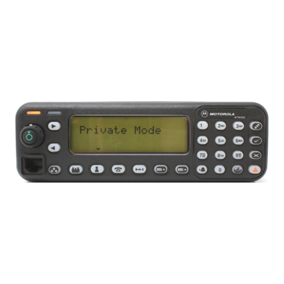
Dimetra MTM300
Motorola Dimetra MTM300 Manuals
Manuals and User Guides for Motorola Dimetra MTM300. We have
1
Motorola Dimetra MTM300 manual available for free PDF download: Installation Instructions Manual
Motorola Dimetra MTM300 Installation Instructions Manual (58 pages)
Brand:
Motorola
| Category:
Radio
| Size: 1.62 MB
Table of Contents
Manual Revisions
2
Computer Software Copyrights
2
Table of Contents
3
1 Safety and General Information
9
Important Information on Safe and Efficient Operation Read this Information before Using Your Radio
9
Radio Frequency (RF) Operational Characteristics
9
Radio Operation and EME Exposure
9
Antenna Care
10
Approved Accessories
10
Electromagnetic Interference/Compatibility
10
Facilities
10
Medical Devices
10
Safety and General
11
Operational Warnings
11
Mobile Radio Operation and EME Exposure
12
Antenna Installation
12
Mobile Antennas
12
Fixed Site Antennas
12
Table 1 Rated Power and Lateral Distance
12
Antenna Product Information
13
EMC Guidelines
13
European Union Directives Conformance Statement
13
Table 2 Antenna Product Information
13
2 Dash Mounting
15
General
15
Installation Planning
15
Figure 1 Example of Top or under Dash Mounting
15
Figure 2 Example of in Dash Mounting
16
Figure 3 Dash Mount Installation
16
Trunnion Installation
17
Radio Installation and Connections
17
Figure 4 Dash Mount Installation with Data Adapter FLN2659 (for Data Applications)
17
Figure 5 Strain Relief Clip Installation
18
Figure 6. Trunnion Mount-Transmission Hump Mounting
18
Figure 7 Trunnion Mount-Below Dash Mounting
18
Optional HLN6372 Keylock Installation
19
Figure 8 Connections to Radio
19
Figure 9 Optional Keylock Installation
19
Power Cable Installation
20
Figure 10 Cable Routing into Engine Compartment
20
Microphone Installation
21
Speaker Installation
21
Introduction
21
Figure 11 Power Cable Assembly
21
Installation Instructions for Accessory Plug
22
Introduction
22
Disassembling and Reassembling Accessory Plug
22
Disassembly
22
Figure 12 Mounting Speaker under Dashboard
22
Reassembly
23
Figure 13 Disassembling and Reassembling Accessory Plug - Disassembly
23
Connection Plan for Speaker, Hands-Free Microphone, and PTT Switch
24
Connection Plan for Alarm Relay
24
Figure 14 Speaker, Hands-Free Microphone, and PTT Switch Connection Plan
24
Figure 15 Alarm Relay Connection Plan
24
Connection Plan for Emergency Switch
25
Connection Plan and Installation of Ignition Sense Cable
25
Figure 16 Connection Plan for Emergency Switch
25
Figure 17 Connection Plan for Ignition Sense Cable
25
Installation of Ignition Sense Cable
26
3 Remote Mounting
27
General
27
Installation Planning
27
Figure 18 Example of Remote Mounting
28
Figure 19 Remote Mount Installation (Data Junction Box Shown)
28
Installing and Connecting the MTM300
29
Transceiver Trunnion Installation
29
Transceiver Installation
29
Figure 20 Transceiver Trunnion Mounting
29
Transceiver Connections
30
Control Head Mounting Trunnion Installation
30
Figure 21 Connections to Radio
30
Figure 22 Control Head Mounting Trunnion
30
Control Head Installation
31
Control Head Connections
31
Junction Box Installation and Connections
31
Installation
31
Connections
31
Table 3 Mechanical Parts for Control Head Mounting Trunnion
31
Optional HLN6372 Keylock Installation
32
Figure 23 Connections to Junction Box
32
Figure 24 Optional Keylock Installation
32
Table 4 Mechanical Parts for FLN2451 Junction Box and FLN2483 Data Junction Box
32
Power Cable Installation
33
Figure 25 Cable Routing into Engine Compartment
33
Microphone Installation
34
Figure 26 Power Cable Assembly
34
Speaker Installation and Connection
35
Introduction
35
Speaker Installation
35
Figure 27 Mounting Speaker under Dashboard
35
Accessory Plug Removal
36
Speaker Connection
36
Figure 28 Disassembling and Reassembling Accessory Plug - Disassembly
36
Figure 29 Speaker Connection
36
Connections Plans for Junction Box Terminal
37
Connection Plan for Speaker
37
Connection Plan for Alarm Relay
37
Connection Plan for Emergency Switch
37
Figure 30 Alarm Relay Connection Plan
37
Figure 31 Emergency Switch Connection Plan
37
Connection Plan and Installation of Ignition Sense Cable
38
Figure 32 Connection Plan for Ignition Sense Cable
38
4 Desktop Mounting
39
General
39
Installation Planning
39
Figure 33 Desktop Installation (with Tray HLN6404)
39
Desktop Installation
40
Figure 34 Desktop Installation with Tray HLN6405 and Data Adapter FLN2659 (for Data Applications)
40
Figure 35 Connecting the Speaker Cable
40
Installation Instructions for Accessory Plug
41
Disassembling and Reassembling Accessory Plug
41
Disassembly
42
Figure 36 Disassembling and Reassembling Accessory Plug - Disassembly
42
Reassembly
43
Figure 37 Connection Plan for Speaker
43
Desktop Tray HLN6404
44
Figure 38 Desktop Tray HLN6404
44
Table 5 Mechanical Parts for Desktop Tray HLN6404
44
5 Motorcycle Installation
45
General
45
Installation Planning
45
Figure 39 Remote Mount Motorcycle Installation Overview
46
Figure 40 Example of Motorcycle Installation
47
Figure 41 Example of External PTT Controlled Installation
47
Figure 42 Example of Manual Select between "Front" and "Back" Use of Microphone and Loudspeaker
48
Figure 43 Example of Installation with Serial Resistor for Volume Adjustment
48
Installing and Connecting the MTM300
49
Transceiver Trunnion Installation
49
Transceiver Installation
49
Figure 44 Example of Installation with Microphone Interface
49
Transceiver Connections
50
Control Head Mounting Trunnion Installation
50
Figure 45 Transceiver Trunnion Mounting
50
Figure 46 Connections to Radio
50
Control Head Installation
51
Figure 47 Control Head Mounting Trunnion
51
Figure 48 Ground Control Head as Shown
51
Table 6 Mechanical Parts for Control Head Mounting Trunnion (Motorcycle Version)
51
Control Head Connections
52
Junction Box Installation and Connections
52
Installation
52
Connections
52
Figure 49 Wiring Diagram
52
Antenna Mounting
53
Power Cable Installation
53
Figure 50 Connections to Junction Box
53
Table 7 Mechanical Parts for FLN2451 Junction Box and FLN2483 Data Junction Box
53
Microphone Installation
54
Figure 51 Power Cable Assembly
54
Speaker Installation and Connection
55
Introduction
55
Speaker Installation
55
Speaker Connection
55
Figure 52 Example of Mounting Speaker Trunnion in Motorcycle Box
55
Figure 53 Speaker Connection
55
Figure 54 Alarm Relay Connection Plan
56
Figure 55 Emergency Switch Connection Plan
56
Connections Plans for Junction Box Terminal
56
Figure 56 Connection Plan for Ignition Sense Cable
57
Advertisement
Advertisement
Related Products
Motorola MTM700
Motorola Malux MTM5x00 Series
Motorola MTM800E
Motorola MTM5 00 Series
Motorola TETRA MTM5000 Series
Motorola MTP6750
Motorola MTP3150
Motorola MR 11** TD-R
Motorola MWR815
Motorola Radius M33DGC00A1AA
Motorola Categories
Cell Phone
Two-Way Radio
Baby Monitor
Cordless Telephone
Radio
More Motorola Manuals
Login
Sign In
OR
Sign in with Facebook
Sign in with Google
Upload manual
Upload from disk
Upload from URL