Advertisement
Table of Contents
Advertisement
Table of Contents

Summary of Contents for Gallien-Krueger 200MB
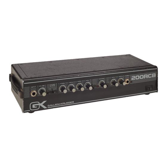
- Page 1 Service Manual 200MB...
- Page 2 Table of Contents Operating Instructions Turn On / Calibration Procedure Schematics Engineering Change Orders (ECOs) 18 Bill of Materials...
- Page 6 200MB/RCB T/O Procedure Rev.B- 3/7/88 Inspect board. Connect mains. Observe the following: A) no load E) volume on 0 I) chorus depth on 0 B) variac at 0 F) master on 0 J) chorus rate on 0 C) trim pots halfway...
- Page 7 Note: Trigger is on the channel, the scope probe is on, and connect to D.0 (J5) @ 1V/div. This will make it possible to make measurements without having trigger problems. An external trigger could also be used. A) Volume at 9 o’clock B) Master at 10.
- Page 19 200MB INDENTED BILL OF MATERIALS SW- Rev. 8/27/99 NOTE: Level 1 refers to main assembly parts. Level 2 refers to board level components. Main assembly numbers are in bold face, while commonly needed parts are italicized. LVL PART# DESCRIPTION QTY REF. DESIG.
- Page 20 132-0351-B 200MB-MK LEFT SIDE 114-6046-0 NUT 10-32 CAPTIVE 120-0005-0 ALUM .100 132-0352-B 200MB BAFFLE 120-0005-0 ALUM .100 132-0356-B 200MK GRILL 120-0003-0 STEEL,16GA,PERF,3’X10’X.060 120-0011-0 STEEL,18 GAUGE JET COAT,.048 132-0384-B 200MB FRONT PANEL SERIES 2 112-6016-0 NUT 6-32 CAPTIVE 120-0007-0 ALUM .063...
- Page 21 LVL PART# DESCRIPTION QTY REF. DESIG. 132-0385-B 200MB REAR PANEL SERIES 2 112-6016-0 NUT 6-32 CAPTIVE 120-0005-0 ALUM .100 132-0386-D 200MB BACK SERIES 2 120-0005-0 ALUM .100 160-0008-0 MANUAL,MB-RCB SERIES II 202-0014-0 200MB WIRE KIT 206-0056-G 200MB-RCB II AMP 001-0006-0...
- Page 22 LVL PART# DESCRIPTION QTY REF. DESIG. 030-2332-0 CAP,CERAMIC AXIAL,332,10%,50V 030-2470-0 CAP,CERAMIC AXIAL,47,5%,50V C79A 030-2473-0 CAP,CERAMIC AXIAL XR7,473,10%,50V C61,64 030-2474-0 CAP,CERAMIC AXIAL Z5U,474,20%,50V C31,45,49 030-2561-0 CAP,CERAMIC AXIAL,561,10%,50V 031-1227-0 CAP,ELECTROLYTIC RADIAL,227,-10%+50%,25V 10 C3,42,55,57,58,59,60,88,99,103 031-2106-0 CAP,ELECTROLYTIC RADIAL,106,-10%+50%,50V 2 C90,91 031-2227-0 CAP,ELECTROLYTIC RADIAL,227,-10%+50%,50V 1 031-2335-0 CAP,ELECTROLYTIC RADIAL,335,20%,50V C4,6,7,8,9,10,11,13,14,15,16,19,20,22,24,26,46,47,...
- Page 23 090-0013-0 SWITCH,PP,DPDT,.2A,PC MOUNT 092-0201-0 JACK SW-RN112APC,1/4",S-TIP,SLDR TERM J1,6-input 092-0202-0 JACK SW-RN114BPC,1/4",S-TIP,S-RING,P.C. 092-0203-0 JACK SW-RN111PC,1/4",O-TIP,P.C. TERM J4,7,10 092-0204-0 JACK SW-RN112BPC,1/4",O-TIP,O-RING,P.C. 093-0028-0 HEADER,3X.156,MALE,LOCK FOR POWER AND SPEAKER CUT-OFF 100-0028-0 BUTTON,SQUARE BLACK CAP - MINI SWITCH 145-0056-G 200MB BOARD P.C.B. 602-0007-0 FORMS,WARRANTY CARDS...


