Advertisement
Quick Links
Thank you for purchasing a Sealey product. Manufactured to a high standard this product will, if used according to these instructions
and properly maintained, give you years of trouble free performance.
IMPORTANT: PLEASE READ THESE INSTRUCTIONS CAREFULLY. NOTE THE SAFE OPERATIONAL REQUIREMENTS, WARNINGS & CAUTIONS.
USE THIS PRODUCT CORRECTLY AND WITH CARE FOR THE PURPOSE FOR WHICH IT IS INTENDED. FAILURE TO DO SO MAY CAUSE DAM-
AGE OR PERSONAL INJURY, AND WILL INVALIDATE THE WARRANTY. PLEASE KEEP INSTRUCTIONS SAFE FOR FUTURE USE.
1. SAFETY INSTRUCTIONS
1.2
GENERAL SAFETY
! Familiarise yourself with this products application and limitations, as well as the specific potential hazards peculiar to the press.
! Maintain the press in good condition (use an authorised service agent).
! Replace or repair damaged parts. Use recommended parts only. Non authorised parts may be dangerous and will invalidate the warranty.
! Keep the press clean for best and safest performance.
! Locate the press in an adequate working area for its function, keep area clean and tidy and free from unrelated materials, and ensure
there is adequate lighting.
! Ensure the workpiece is correctly secured before operating the press.
F WARNING! Always wear approved eye or face protection when operating the press.
! Remove ill fitting clothing. Remove ties, watches, rings, and other loose jewellery, and contain long hair.
! Keep hands and body clear of the work table when operating the press.
! Maintain correct balance and footing. Ensure the floor is not slippery and wear non slip shoes.
! Keep children and unauthorised persons away from the working area.
% DO NOT operate the press if any parts are missing as this may cause failure or possible personal injury.
% DO NOT force the press to achieve a task it was not designed to perform.
% DO NOT adjust or tamper with the safety valve.
% DO NOT exceed the rated capacity of the press.
% DO NOT apply off centre loads.
% DO NOT allow the workpiece of the arbor plates to fall from the press working bench.
% DO NOT get the press wet or use in damp or wet locations or areas where there is condensation.
% DO NOT operate the press when you are tired, under the influence of alcohol, drugs or intoxicating medication.
! When not in use release pressure from the pump and clean the press. Stand or store the arbors in a safe location.
2. INTRODUCTION & SPECIFICATIONS
2.1.
GENERAL INFORMATION
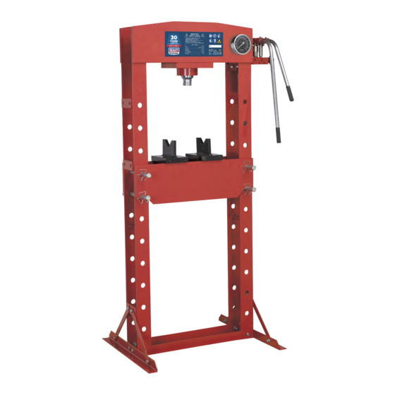
Heavy-duty press frame with integrally mounted air motor powering reliable hydraulic pump unit. Reinforced frame head fitted with sliding
hydraulic ram assembly giving 250mm of lateral travel for off-centre pressing applications. Fitted with ram pressure gauge and table winch aiding
exact alignment of the ram head and workpiece. Supplied with a pair of V-blocks.
F
F
WARNING! All models are purpose designed to withstand greater loads than the hydraulic units can develop. For safety reasons, always
ensure the workpiece is secured on table and loads that flex will not suddenly “give” causing danger to operator or damage to component.
p
p
2.2. SPECIFICATIONS
Model:
Capacity
Ram Stroke
Extension screw
Lateral ram travel
Max Ht-ram to table
Min Ht-ram to table
Table Aperture
Work table width
Overall Height
Gauge Included
Weight
3. ASSEMBLY
F WARNING! This equipment is very heavy! 2 - 3 people will be required to manoeuver the components during assembly.
Ensure correct form is observed where lifting is involved and that all health and safety precautions regarding the movement/use of such
equipment are observed.
Unpack product and check contents against list below. Should there be any damaged or missing parts contact your supplier immediately.
Retain pressure gauge in carton until required, and do not remove white tape from gauge mount.
Contents:
!Frame !legs x2 !worktable x1 !worktable pins x2 !v-blocks x2 !pump handle x1 !pressure gauge + adaptor x1 !Winch handle.
3.1.
Press Assembly
3.1.1. Identity and lay out parts. Handle the main frame with care and lay horizontally allowing the cross legs to be bolted on to the bottom
of the pre-assembled main frame. Note: care must be taken when handling the main frame to ensure stability. DO NOT allow to fall.
3.1.2. Locate the pressure gauge hole in the head of the press hydraulic system and remove the dust plug with a hex key, (this may
be very tightly secured).
Screw the gauge adaptor tightly into this hole, now screw the gauge into the adaptor, ensuring that the gauge comes to rest in an
upright position for ease of reading.
YK30 FAH
YK50 FAH
30ton
50ton
95mm
95mm
75mm
75mm
250mm
250mm
615mm
615mm
165mm
165mm
145mm
145mm
710mm
710mm
1770mm
1810mm
Yes
Yes
202kg
220kg
INSTRUCTIONS FOR:
AIR HYDRAULIC FLOOR PRESS
Models:
YK30FAH, YK50FAH
YK30FAH & YK50FAH - 1 - 250703
Advertisement

Summary of Contents for Sealey YK30FAH
- Page 1 Models: YK30FAH, YK50FAH Thank you for purchasing a Sealey product. Manufactured to a high standard this product will, if used according to these instructions and properly maintained, give you years of trouble free performance. IMPORTANT: PLEASE READ THESE INSTRUCTIONS CAREFULLY. NOTE THE SAFE OPERATIONAL REQUIREMENTS, WARNINGS & CAUTIONS.
- Page 2 Should you need to replace oil ensure piston is fully retracted. An excess of oil will render press inoperative. Use only appropriate Sealey hydraulic oil. DO NOT use brake fluid. Contact your local Sealey dealer for details. Purge the system to remove any air.


