Sign In
Upload
Manuals
Brands
Sony Manuals
Camcorder
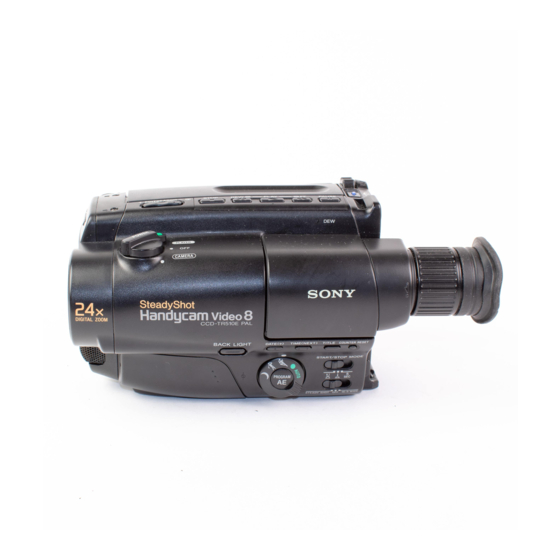
CCD-TR330E
User Manuals: Sony CCD-TR330E Camcorder
Manuals and User Guides for Sony CCD-TR330E Camcorder. We have
1
Sony CCD-TR330E Camcorder manual available for free PDF download: Service Manual
Sony CCD-TR330E Service Manual (277 pages)
Video Camera Recorder
Brand:
Sony
| Category:
Camcorder
| Size: 18.82 MB
Table of Contents
Specifications
1
Checking Supplied Accessories
2
Safety Check-Out
2
Table of Contents
3
How to Remove Cassette if the Main Power Cannot be Switched on
5
Checking Your Model Number
6
Charging and Installing the Battery Pack
6
Inserting a Cassette
8
Camera Recording
9
Hints for Better Shooting
11
Checking the Recorded Picture
12
Connections for Playback
13
Playing Back a Tape
14
Using Alternate Power Sources
15
Shooting with Backlighting
17
Recording with the Date or Time
17
Using the PROGRAM AE Function
18
Shooting Scenery in Several Short Takes
19
Superimposing a Title
19
Using the Steady Shot Function
20
Using the Wide Mode Function
20
Editing Onto Another Tape
21
Changing the Mode Settings
21
Changing the Lithium Battery in the Camcorder
23
Playback Modes
24
Tips for Using the Battery Pack
24
Resetting the Date and Time
24
Notes on the Battery Case
26
Notes on Charging
26
Notes on the Terminals
26
Maintenance Information and Precautions
27
Using Your Camcorder Abroad
30
Identifying the Parts
31
Remote Controller Parts
33
Attaching the Shoulder Strap
33
Remote Control Direction
34
Preparing the Remote Commander
34
Using the Remote Commander
34
To Watch the Demonstration
35
In the Viewfinder
35
Warning Indicators
36
Disassembly
37
Removal of F Panel Assy, MA-238 Board and Microphone
37
Removal of Cabinet Assy
37
Removal of CF-40 Board
38
Removal of PW-108 Board
38
Removal of EVF Block Assy
39
Removal of CRT Assy and VF-87P Board
39
Internal Views
40
Circuit Boards Location
41
Overall Block Diagram
42
Camera Block Diagram
45
Video/Audio Block Diagram
48
System Control Block Diagram
51
Servo Block Diagram
53
Mode Control/Evf Block Diagram
56
Power Block Diagram
59
Printed Wiring Boards and Schematic Diagrams
62
Frame Schematic Diagram
62
Precautions Upon Replacing CCD Imager
71
VC-167P, FP-249 Schematic Diagrams
92
VC-167P, MA-238 Schematic Diagrams
95
DD-80P Printed Wiring Board
100
DD-80P, VC-167P Schematic Diagrams
102
FP-249 Printed Wiring Board
105
VC-167P Printed Wiring Board
108
CF-40, PW-108 Printed Wiring Boards
112
CF-40, PW-108 Schematic Diagram
115
VF-87P, JK-129, CD-139 Printed Wiring Boards and Schematic Diagram
121
VF-87P Schematic Diagram
127
TZ-3 (Steady Shot) Printed Wiring Board
129
TZ-3 Schematic Diagram
131
Repair Parts List
134
Exploded Views
134
Cabinet(L), F Panel Section View
135
Cabinet(R) Section View
136
EVF Section Parts
137
Main Section Parts
138
Cassette Compartment Block Section Parts
139
LS Chassis Block Section Parts
140
Mechanism Chassis Block Section Parts
141
Electrical Parts List
142
Camera Section Adjustment
158
Camera Section Adjustment Switch Settings
159
Camera Section Adjustment Subject
159
Adjustment Remote Commander (RM-95 Upgraded)
161
Page F Address List
163
Adjustment Points When Major Parts Have Been Replaced
165
Preparation for Camera System Adjustment
165
Power Supply Voltage Check(VC-167P Board)
165
Initialization of Page F Data
166
V SUB Adjustment
167
VRG Adjustment
167
Page F Data Modification
168
28 Mhz Crystal Oscillator Adjustment
169
Hall Adjustment
171
Flange Back Adjustment
173
Picture Frame Setting
175
Color Reproduction Adjustment
176
IRIS IN/OUT Adjustment
177
MAX Gain Adjustment
178
Auto White Balance Reference Data Input
179
Auto White Balance Adjustment
180
White Balance Check
181
Camera-Shaking Correction Adjustment
182
Electronic Viewfinder System Adjustments (VF-87P Board)
183
Arrangement Diagram for Adjustment Parts
185
Mechanism Section Adjustments
186
How to Operate Mechanism after the Cassette Compartment Is Removed
186
Tape Path Adjustment
187
Video Section Adjustment
188
Preparations before Adjustment
189
Adjustment Points When Major Parts Are Replaced
192
Power Supply System Adjustment
192
Servo System Adjustments
199
SYNC Level and BURST Level Adjustments
199
Switching Position Adjustment
200
Capstan FG Offset Adjustment
201
Playback Frequency Response Characteristics Adjustment
202
DEMD out Level Adjustment
203
YD out Level Adjustment
204
PB Chroma Level Check
205
PB y out Level Adjustment
206
FE OSC Check
207
Emphasis Input Level Adjustment
208
Y FM Deviation Adjustment(Note)
209
Y FM Carrier Frequency Adjustment
210
Chroma Emphasis Fo Adjustment
211
REC y Level Adjustment
212
Rec L Level Adjustment
213
Rec C Level Adjustment
214
Audio System Adjustment
215
1.5Mhz Deviation Adjustment
216
BPF Fo Adjustment
217
Overall Signal Level and Distortion Check
218
Overall Noise Level Check
218
Arrangement Diagram for Adjustment Parts VC-167P Board
219
For Camera Color Reproduction Adjustment (CCD-TR330E Model)
220
B-Mechanism: Contents
222
Table of B-Mechanism Know-How
226
Tape Not Wound
231
No Eject (Trouble with M Slider at Unloading)
237
Threading Not Completed (Change V-Shaped Drum Base)
244
Damage to Tape Due to Slack of T Side Tape
253
Tape Not Ejected (Capstan Motor Not Rotating)
255
Unification of Improvements "T. Reel Height Change" for the Trouble of Reel Does Not Wind Tape
273
Specification Change of B Mechanism Reel Table Torque
274
Remedy When Grease Is Attached to Tape
275
Advertisement
Advertisement
Related Products
Sony Handycam CCD-TR3300
Sony Handycam CCD-TR33
Sony Handycam CCD-TR330PK
Sony Handycam CCD-TR330
Sony CCD-TR3300E
Sony Handycam CCD-TR317
Sony Handycam Video 8 XR CCD-TR316
Sony HandyCam video Hi8 XR CCD-TR3200E Hi8
Sony CCD-TR3400E
Sony CCD-TR3100E
Sony Categories
Laptop
TV
CD Player
Camcorder
Digital Camera
More Sony Manuals
Login
Sign In
OR
Sign in with Facebook
Sign in with Google
Upload manual
Upload from disk
Upload from URL