Sign In
Upload
Manuals
Brands
Siemens Manuals
Controller
6MD85
Siemens 6MD85 Bay Controller Manuals
Manuals and User Guides for Siemens 6MD85 Bay Controller. We have
2
Siemens 6MD85 Bay Controller manuals available for free PDF download: Manual, Technical Data Manual
Siemens 6MD85 Manual (1256 pages)
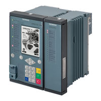
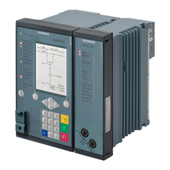
SIPROTEC 5 High-Voltage Bay Controller
Brand:
Siemens
| Category:
Controller
| Size: 36.55 MB
Table of Contents
Preface
3
Open Source Software
7
Table of Contents
9
1 Introduction
31
General
32
Properties of SIPROTEC 5
34
2 Basic Structure of the Function
35
Function Embedding in the Device
36
Adjustment of Application Templates/Functional Scope
38
Function Control
40
Text Structure and Reference Number for Settings and Indications
44
Information Lists
45
3 System Functions
47
Indications
48
General
48
Reading Indications on the On-Site Operation Panel
48
Reading Indications from the PC with DIGSI 5
50
Displaying Indications
51
Logs
53
General
53
Operational Log
55
Fault Log
56
Ground-Fault Log
57
Setting-History Log
59
User Log
61
Security Log
63
Device-Diagnosis Log
64
Communication Log
65
Motor-Starting Log
66
Saving and Deleting the Logs
68
Spontaneous Indication Display in DIGSI 5
69
Spontaneous Fault Display on the On-Site Operation Panel
70
Stored Indications in the SIPROTEC 5 Device
71
Resetting Stored Indications of the Function Group
72
Test Mode and Influence of Indications on Substation Automation Technology
72
Measured-Value Acquisition
73
Processing Quality Attributes
75
Overview
75
Quality Processing/Affected by the User for Received GOOSE Values
77
Quality Processing/Affected by the User in CFC Charts
83
Quality Processing/Affected by the User in Internal Device Functions
87
Fault Recording
91
Overview of Functions
91
Structure of the Function
91
Function Description
91
Application and Setting Notes
94
Settings
96
Information List
96
Protection Communication
97
Overview
97
Protection Interface and Protection Topology
97
Overview of Functions
97
Structure of the Function
97
Function Description
98
Initialization and Configuration of the Protection Interface in DIGSI 5
108
Device-Combination Settings
109
Selecting the Connection
111
Routing Information in DIGSI 5
112
Diagnostic Measured Values of the Protection Interface
118
Diagnostic Data for the Protection Interface
122
Settings
126
Information List
127
Date and Time Synchronization
129
Overview of Functions
129
Structure of the Function
129
Function Description
129
Application and Setting Notes
132
Settings
135
Information List
136
User-Defined Objects
137
Overview
137
Basic Data Types
138
Pulse- and Energy- Metered Values
141
Additional Data Types
141
External Signals
141
Other Functions
143
Signal Filtering and Chatter Blocking for Input Signals
143
Acquisition Blocking and Manual Updating
147
Persistent Commands
149
Device Logoff
150
Overview
150
Application and Setting Notes
151
Information List
153
General Notes for Setting the Threshold Value of Protection Functions
154
Overview
154
Modifying the Transformer Ratios in DIGSI 5
154
Changing the Transformation Ratios of the Transformer on the Device
161
Device Settings
162
Settings-Group Switching
162
Overview of Functions
162
Structure of the Function
162
Function Description
162
Application and Setting Notes
163
Settings
164
Information List
164
General Device Settings
164
Overview
164
Application and Setting Notes
166
Settings
167
Information List
167
Device Logoff
168
Overview
168
Application and Setting Notes
169
Information List
170
Security Settings in the Device
171
Multi-Level Safety Concept
171
4 Applications
173
Overview
174
Application Templates and Functional Scope for Device 6MD85
175
Application Templates and Functional Scope for Device 6MD86
178
5 Function-Group Types
181
Power-System Data
182
Overview
182
Structure of the Power-System Data
182
Application and Setting Notes - General Settings
182
Application and Setting Notes for Measuring Point Voltage 3-Phase (V-3Ph)
183
Application and Setting Notes for Measuring Point Current 3-Phase (I-3Ph)
186
Settings
189
Information List
191
Function-Group Type Voltage/Current 3-Phase
193
Overview
193
Structure of the Function Group
193
Application and Setting Notes
197
Write-Protected Settings
198
Settings
198
Information List
198
Function-Group Type Voltage/Current 1-Phase
200
Overview
200
Structure of the Function Group
200
Application and Setting Notes
203
Write-Protected Settings
204
Settings
204
Information List
205
Function-Group Type Voltage 3-Phase
206
Overview
206
Structure of the Function Group
206
Application and Setting Notes
207
Settings
207
Information List
208
Function-Group Type Circuit Breaker, 3-Pole
209
Overview
209
Structure of the Function Group
210
Application and Setting Notes
211
Settings
212
Information List
213
Trip Logic
213
Function Description
213
Application and Setting Notes
214
Settings
215
Information List
215
Circuit Breaker
215
Overview
215
Tripping, Opening, and Closing the Circuit Breaker
215
Acquisition of Circuit-Breaker Auxiliary Contacts and Further Information
216
Circuit-Breaker Tripping Alarm Suppression
218
Tripping and Opening Information
219
Application and Setting Notes
220
Settings
222
Information List
223
Circuit-Breaker Position Recognition for Protection-Related Auxiliary Functions
223
Overview
223
Detection Manual Closure (for AREC and Process Monitor)
224
Function Description
224
Application and Setting Notes
225
Settings
226
Information List
226
Function-Group Type Circuit Breaker, 1-/3-Pole
227
Overview
227
Structure of the Function Group
227
Application and Setting Notes
229
Trip Logic
230
Function Description
230
Application and Setting Notes
234
Settings
236
Information List
236
Circuit Breaker
236
Overview
236
Tripping, Opening, and Closing the Circuit Breaker
236
Acquisition of Circuit-Breaker Auxiliary Contacts and Further Information
238
Definitive Tripping, Circuit-Breaker Tripping Alarm Suppression
239
Tripping and Opening Information
240
Application and Setting Notes
241
Settings
245
Information List
245
Circuit-Breaker Position Recognition for Protection-Related Auxiliary Functions
246
Overview
246
Detection Manual Closure (for AREC and Process Monitor)
247
Function Description
247
Application and Setting Notes
247
Settings
248
Information List
248
Settings
249
Information List
250
Function-Group Type Analog Units
253
Overview
253
Structure of the Function Group
253
20-Ma Unit Ethernet
255
Overview
255
Structure of the Function
255
Communication with 20-Ma Unit Ethernet
256
Application and Setting Notes
257
20-Ma Channel
257
Application and Setting Notes
260
Settings
261
Information List
262
20-Ma Unit Serial
262
Overview
262
Application and Setting Notes
262
Settings
264
Information List
265
Communication with 20-Ma Unit
265
Integration of a Serial 20-Ma Unit
265
Integration of a 20-Ma Unit Ethernet
268
V/I-Measuring-Transducer Unit with Fast Inputs
270
Overview
270
Structure of the Function
271
Function Description
271
Application and Setting Notes
272
Settings
276
Information List
278
RTD Unit Ethernet
278
Overview
278
Structure of the Function
278
Communication with an RTD Unit
279
Application and Setting Notes
280
Temperature Sensor
281
Application and Setting Notes
281
Settings
282
Information List
282
RTD Unit, Serial
283
Overview
283
Application and Setting Notes
283
Settings
284
Information List
285
Communication with RTD Unit
286
Integration of a Serial RTD Unit (Ziehl TR1200)
286
Integration of an RTD-Unit Ethernet (TR1200 IP)
289
Temperature Simulation Without Sensors
291
Process Monitor
292
Overview of Functions
292
Structure of the Function
292
Current-Flow Criterion
293
Application and Setting Notes (Current-Flow Criterion)
294
Settings
295
Circuit-Breaker Condition for the Protected Object
295
Closure Detection
295
Information List
296
Cold-Load Pickup Detection (Optional)
297
Application and Setting Notes (Cold-Load Pickup Detection)
298
Settings
299
Information List
299
Voltage Measuring-Point Selection
300
Overview of Functions
300
Function Description
300
Application and Setting Notes
301
Information List
302
6 Control Functions
303
Introduction
304
Overview
304
Concept of Controllables
304
Switching Devices
307
General Overview
307
Switching Device Circuit Breaker
307
Structure of the Circuit-Breaker Switching Device
307
Application and Setting Notes
311
Connection Variants of the Circuit Breaker
313
Settings
321
Information List
323
Disconnector Switching Device
325
Structure of the Disconnector Switching Device
325
Application and Setting Notes
329
Trigger Variants of the Disconnector
331
Settings
334
Information List
334
Control Functionality
335
Command Checks and Switchgear Interlocking Protection
335
Command Logging
353
Application Notes and Setting Notes for the External 1-Of-N Check Function Block
358
Settings
359
Information List
359
Synchronization Function
360
Overview of Functions
360
Structure of the Function
360
Connection and Definition
361
General Functionality
365
Description
365
Application and Setting Notes (General)
368
Settings
371
Dynamic Measuring-Point Switching
372
Sequence of Functions
375
Stage Synchrocheck
377
Description
377
Application and Setting Notes
378
Settings
378
Information List
379
Stage Synchronous/Asynchronous
380
Description
380
Application and Setting Notes
384
Settings
386
Information List
387
Stage Synchronous/Asynchronous with Balancing Commands
388
Description
388
Application and Setting Notes
395
Settings
405
Information List
406
Expanded Checks (Df/Dt and Smoothing of Oscillations)
408
Closing at De-Energized Line/Busbar
409
Description
409
Application and Setting Notes
410
Direct Close Command
412
Interaction with Control and External Triggering
413
External Synchronization
414
Description
414
Application and Setting Notes (External Synchronization)
417
Settings
418
Information List
420
Settings
420
Information List
422
Switching Sequences
425
Overview of Functions
425
Function Description
425
Application and Setting Notes
427
Settings
430
Information List
431
User-Defined Function Block [Control]
432
Overview of Functions
432
Function Description
432
Application and Setting Notes
432
Settings
433
Information List
434
CFC-Chart Settings
435
Overview of Functions
435
Function Description
435
Application and Setting Notes
435
Settings
436
Information List
436
Transformer Tap Changers
437
Function Description
437
Application and Setting Notes
441
Settings (Properties Dialog)
447
Settings
448
Information List
448
Voltage Controller
450
Overview of Functions
450
Structure of the Function
450
Function Description
451
General
451
Logic of the Function
458
Control Response
459
Function Supervision
462
Line Compensation
462
Limiting Values
464
Blockings
464
Parallel Control
465
Creating a GOOSE Later Binding for Parallel Control
476
Functional Measured Values
484
Application and Setting Notes
488
General
488
Controlling
490
Voltage Controller
490
Line Compensation
495
Limiting Values
498
Blockings
499
Parallel Control
500
Settings
501
Information List
509
7 Protection and Automation Functions
515
Circuit-Breaker Failure Protection
516
Overview of Function
516
Structure of the Function
516
Function Description
517
Application and Setting Notes
528
Settings
537
Information List
539
Automatic Reclosing Function
542
Overview of Functions
542
Structure of the Function
542
Cooperation of the Automatic Reclosing Function and Protection Functions
544
Cyclic Automatic Reclosing Function
546
Operating Modes for Cyclic Automatic Reclosing Function
546
Structure of the Cyclic Automatic Reclosing Function
549
Input Logic for Operating Modes with Tripping
550
Input Logic for Operating Modes with Pickup
551
Start
552
Cycle Control with Operating Mode 1: with Tripping/With Action Time
553
Cycle Control with Operating Mode 2: with Pickup/With Action Time
555
Cycle Control with Operating Mode 3: with Tripping/Without Action Time
557
Cycle Control with Operating Mode 4: with Pickup/Without Action Time
558
Stage Release
559
Dead Time for Operating Modes with Tripping
560
Dead Time for Operating Modes with Pickup
562
Evolving-Fault Detection During Dead Time
564
Closing Indication and Close Command
566
Reclaim Time
568
Circuit-Breaker Readiness and Circuit-Breaker Condition
569
Blockings
571
Dead-Line Checking (DLC) and Reduced Dead Time (RDT)
574
Settings
576
Information List
578
Automatic Reclosing Function with Adaptive Dead Time (ADT)
580
Description
580
Settings
581
Information List
581
Cooperation with External Automatic Reclosing Function
583
Description
583
Information List
584
Application and Setting Notes for General Settings
585
Application and Setting Notes for 1 Cycle of the Cyclic Automatic Reclosing Function
591
Information List
594
External Trip Initiation 3-Pole
595
Overview of Functions
595
Structure of the Function
595
Stage Description
596
Application and Setting Notes
596
Settings
596
Information List
597
Overcurrent Protection, Phases
598
Overview of Functions
598
Structure of the Function
598
Filter for RMS Value Gain
599
Description
599
Application and Setting Notes
600
Settings
601
Information List
602
Stage with Definite-Time Characteristic Curve
602
Description
602
Application and Setting Notes
606
Settings
609
Information List
611
Stage with Inverse-Time Characteristic Curve
613
Description
613
Application and Setting Notes
617
Settings
620
Information List
622
Stage with User-Defined Characteristic Curve
622
Description
622
Application and Setting Notes
624
Settings
625
Information List
628
Blocking of the Tripping by Device-Internal Inrush-Current Detection
628
Description
628
Application and Setting Notes
629
Influence of Other Functions Via Dynamic Settings
629
Description
629
Application and Setting Notes (Advanced Stage)
633
Overcurrent Protection, Ground
634
Overview of Functions
634
Structure of the Function
634
General Functionality
635
Description
635
Application and Setting Notes
636
Settings
637
Stage with Definite-Time Characteristic Curve
638
Description
638
Application and Setting Notes
640
Settings
642
Information List
647
Stage with Inverse-Time Characteristic Curve
648
Description
648
Application and Setting Notes
651
Settings
652
Information List
655
Stage with User-Defined Characteristic Curve
655
Description
655
Application and Setting Notes
657
Settings
658
Information List
660
Blocking of the Tripping by Device-Internal Inrush-Current Detection
661
Description
661
Application and Setting Notes
661
Influence of Other Functions Via Dynamic Settings
662
Description
662
Application and Setting Notes (Advanced Stage)
666
Directional Overcurrent Protection, Phases
667
Overview of Functions
667
Structure of the Function
667
Stage Control
667
Description
667
Application and Setting Notes
668
Stage with Definite-Time Characteristic Curve
669
Description
669
Application and Setting Notes
672
Settings
674
Information List
679
Stage with Inverse-Time Characteristic Curve
680
Description
680
Application and Setting Notes
683
Settings
685
Information List
688
Stage with User-Defined Characteristic Curve
689
Description
689
Application and Setting Notes
690
Settings
691
Information List
693
Direction Determination
694
Description
694
Application and Setting Notes
696
Influence of Other Functions Via Dynamic Settings
697
Application Notes for Parallel Lines
697
Application Notes for Directional Comparison Protection
698
Directional Overcurrent Protection, Ground
700
Overview of Functions
700
Structure of the Function
700
General Functionality
702
Measured-Value Selection
702
Direction Determination
703
Application and Setting Notes
705
Settings
707
Information List
708
Stage Control
708
Description
708
Application and Setting Notes
708
Stage with Definite-Time Characteristic Curve
710
Description
710
Application and Setting Notes
713
Settings
715
Information List
718
Stage with Inverse-Time Characteristic Curve
719
Description
719
Application and Setting Notes
723
Settings
726
Information List
728
Stage with Inverse-Time Overcurrent Protection with Logarithmic-Inverse Characteristic Curve
730
Description
730
Application and Setting Notes
732
Settings
733
Information List
735
Stage with Knee-Point Characteristic Curve
736
Description
736
Application and Setting Notes
737
Settings
738
Information List
739
Stage with User-Defined Characteristic Curve
740
Description
740
Application and Setting Notes
741
Settings
742
Information List
745
Influence of Other Functions Via Dynamic Settings
745
Overcurrent Protection, 1-Phase
746
Function Overview
746
Structure of the Function
746
Stage with Definite-Time Characteristic Curve
748
Description
748
Application and Setting Notes
749
Settings
750
Information List
750
Stage with Inverse-Time Characteristic Curve
752
Description
752
Application and Setting Notes
753
Settings
754
Information List
755
Stage with User-Defined Characteristic Curve
755
Description
755
Application and Setting Notes
756
Settings
757
Information List
758
Group Indications of Overcurrent Protection Functions
759
Description
759
Inrush-Current Detection
760
Overview of Functions
760
Structure of the Function
760
Function Description
760
Application and Setting Notes
764
Settings
765
Information List
766
Instantaneous High-Current Tripping
767
Overview of Functions
767
Structure of the Function
767
Standard Release Procedure
768
Application and Setting Notes
769
Release Procedure Via Protection Interface
770
Application and Setting Notes
772
Settings
772
Information List
772
Voltage-Dependent Overcurrent Protection
774
Overview of Functions
774
Structure of the Function
774
Stage Description Overcurrent Protection, Voltage-Dependent
775
Description
775
Application and Setting Notes
777
Settings
779
Information List
779
Stage Description Voltage-Independent Overcurrent Protection
780
Description
780
Application and Setting Notes
781
Settings
782
Information List
782
Overvoltage Protection with 3-Phase Voltage
783
Overview of Functions
783
Structure of the Function
783
Description
784
Application and Setting Notes
785
Settings
787
Information List
787
Description
789
Application and Setting Notes
791
Settings
793
Information List
793
Overvoltage Protection with Positive-Sequence Voltage
795
Overview of Functions
795
Structure of the Function
795
Stage Description
796
Application and Setting Notes
796
Settings
797
Information List
797
Overvoltage Protection with any Voltage
799
Overview of Functions
799
Structure of the Function
799
Stage Description
800
Application and Setting Notes
801
Settings
803
Information List
803
Undervoltage Protection with 3-Phase Voltage
805
Overview of Functions
805
Structure of the Function
805
Description
806
Application and Setting Notes
808
Settings
809
Information List
810
Description
811
Application and Setting Notes
815
Settings
816
Information List
817
Undervoltage Protection with any Voltage
818
Overview of Functions
818
Structure of the Function
818
Stage Description
819
Application and Setting Notes
820
Settings
822
Information List
823
Overfrequency Protection
824
Overview of Functions
824
Structure of the Function
824
Overfrequency-Protection Stage
825
Application and Setting Notes
826
Settings
827
Information List
828
Underfrequency Protection
829
Overview of Functions
829
Structure of the Function
829
Underfrequency-Protection Stage
830
Application and Setting Notes
831
Settings
832
Information List
833
Underfrequency Load Shedding
834
Overview of Functions
834
Structure of the Function
834
General Functionality
835
Description
835
Application and Setting Notes
838
Stage Description
841
Description
841
Application and Setting Notes
843
Settings
844
Information List
844
Rate of Frequency Change Protection
846
Overview of Functions
846
Structure of the Function
846
General Functions (Undervoltage Test, Df/Dt Calculation)
846
Description
846
Application and Setting Notes
847
Stage Description
848
Description
848
Application and Setting Notes
849
Settings
850
Information List
850
Power Protection (P,Q), 3-Phase
852
Overview of Functions
852
Structure of the Function
852
Active Power Stage
853
Reactive Power Stage
855
Application Example
856
Setting Notes for the Active Power Stage
857
Setting Notes for the Reactive Power Stage
858
Settings
859
Information List
860
Phase-Sequence Switchover
862
Overview of Functions
862
Structure of the Function
862
Function Description
862
Application and Setting Notes
865
Settings
866
Information List
867
Instantaneous Tripping at Switch Onto Fault
868
Overview of Functions
868
Structure of the Function
868
Stage Description
869
Application and Setting Notes
869
Settings
870
Information List
870
Negative-Sequence Protection
871
Overview of Functions
871
Structure of the Function
871
Stage Description
872
Application and Setting Notes
873
Settings
873
Information List
874
Description
875
Application and Settings Notes
876
Settings
877
Information List
877
Thermal Overload Protection, 3-Phase - Advanced
878
Overview of Functions
878
Structure of the Function
878
Filter for RMS Value Gain
878
Description
878
Application and Setting Notes
879
Settings
880
Information List
881
Description
881
Application and Setting Notes
886
Settings
889
Information List
890
Thermal Overload Protection, 1-Phase
892
Overview of Functions
892
Structure of the Function
892
Function Description
893
Application and Setting Notes
896
Settings
900
Information List
901
Temperature Supervision
902
Overview of Functions
902
Structure of the Function
902
Function Description
903
Application and Setting Notes
903
Settings
904
Information List
909
Arc Protection
912
Overview of Function
912
Structure of the Function
912
Function Description
913
Application and Setting Notes - General Settings
915
Application and Setting Notes for the Stage
916
Settings
917
Information List
918
Application Example for Arc Protection with Point Sensors in Operating Mode: Light Only
920
Description
920
Application and Setting Notes
921
Application Example for Arc Protection with Point Sensors in Operating Mode: Light and Current
922
Description
922
Application and Setting Notes
924
Application Example for Arc Protection with Point Sensors Via External Trip Initiation
924
Description
924
Application and Setting Notes
926
Application and Setting Notes for Variant 2 (with Feedback to Feeder Protection Devices)
928
8 Supervision Functions
931
Overview
932
Resource-Consumption Supervision
933
Load Model
933
Function Points
935
CFC Resources
935
Supervision of the Secondary System
938
Overview
938
Measuring-Voltage Failure
938
Overview of Functions
938
Structure of the Function
939
Unbalanced Measuring-Voltage Failure
940
3-Phase Measuring-Voltage Failure
941
Switching Onto a 3-Phase Measuring-Voltage Failure, Low Load
942
Application and Setting Notes
943
Settings
944
Information List
945
Signaling-Voltage Supervision
945
Overview of Functions
945
Structure of the Function
945
Function Description
946
Application and Setting Notes
948
Settings
949
Information List
950
Voltage-Transformer Circuit Breaker
950
Overview of Functions
950
Structure of the Function
950
Function Description
951
Application and Setting Notes
951
Settings
951
Information List
951
Voltage-Balance Supervision
952
Overview of Functions
952
Structure of the Function
952
Function Description
952
Application and Setting Notes
953
Settings
954
Information List
954
Voltage-Sum Supervision
954
Overview of Functions
954
Structure of the Function
955
Function Description
955
Application and Setting Notes
957
Settings
957
Information List
957
Voltage Phase-Rotation Supervision
957
Overview of Functions
957
Structure of the Function
957
Function Description
958
Application and Setting Notes
959
Settings
959
Information List
959
Current-Balance Supervision
959
Overview of Functions
959
Structure of the Function
959
Function Description
960
Application and Setting Notes
961
Settings
962
Information List
962
Current-Sum Supervision
962
Overview of Functions
962
Structure of the Function
963
Function Description
963
Application and Setting Notes
965
Settings
965
Information List
966
Current Phase-Rotation Supervision
966
Overview of Functions
966
Structure of the Function
966
Function Description
967
Application and Setting Notes
968
Settings
968
Information List
968
Trip-Circuit Supervision
968
Overview of Functions
968
Structure of the Function
968
Trip-Circuit Supervision with 2 Binary Inputs
969
Trip-Circuit Supervision with 1 Binary Input
970
Application and Setting Notes
973
Settings
973
Information List
974
Supervision of the Device Hardware
975
Overview
975
Analog-Channel Supervision Via Fast Current-Sum
976
Overview of Functions
976
Structure of the Function
976
Function Description
977
Supervision of Device Firmware
980
Supervision of Hardware Configuration
981
Supervision of Communication Connections
982
Error Responses and Corrective Measures
983
Overview
983
Defect Severity 1
984
Defect Severity 2
987
Defect Severity 3
988
Defect Severity 4 (Group Alarm)
989
Group Indications
991
Advertisement
Siemens 6MD85 Technical Data Manual (129 pages)
High-Voltage Bay Controller, V7.80 and higher
Brand:
Siemens
| Category:
Controller
| Size: 3.91 MB
Table of Contents
Table of Contents
8
General Device Data
10
Protection Interface and Protection Topology
19
Date and Time Synchronization
21
Automatic Reclosing
22
Phasor Measurement Unit
23
Circuit-Breaker Wear Monitoring
24
External Trip Initiation
25
Overcurrent Protection, Phases
26
Overcurrent Protection, Ground
38
Directional Overcurrent Protection, Phases
48
Directional Overcurrent Protection, Ground
54
Inrush-Current Detection
64
Instantaneous High-Current Tripping
65
Stage with Definite-Time Characteristic Curve
66
Stage with Inverse-Time Characteristic Curve
68
Voltage-Dependent Overcurrent Protection, Phases
70
Overvoltage Protection with 3-Phase Voltage
73
Overvoltage Protection with Positive-Sequence Voltage
75
Overvoltage Protection with any Voltage
76
Undervoltage Protection with 3-Phase Voltage
78
Undervoltage Protection with any Voltage
81
Overfrequency Protection
82
Underfrequency Protection
83
Underfrequency Load Shedding
84
Rate of Frequency Change Protection
86
Power Protection (P,Q), 3-Phase
88
Instantaneous Tripping at Switch Onto Fault
89
Circuit-Breaker Failure Protection
90
Negative-Sequence Protection with Definite-Time Characteristic Curve
92
Stage with Inverse-Time Characteristic Curve
93
Thermal Overload Protection, 3-Phase – Advanced
95
Thermal Overload Protection, 1-Phase
99
Temperature Supervision
102
Analog-Units Function Group
103
Advertisement
Related Products
Siemens 6MD86
Siemens 6DR63 Series
Siemens 6ES7 331-7NF10-0AB0
Siemens 6ES7 332-5HF00-0AB0
Siemens 6ES7 332-5HB81-0AB0
Siemens 6ES7 332-7ND00-0AB0
Siemens 6ES7 331-7RD00-0AB0
Siemens 6ES7 332-5TB00-0AB0
Siemens 6DR2410-4
Siemens 6ES7212-0AA50-0AA0
Siemens Categories
Industrial Equipment
Controller
Control Unit
Oven
Washer
More Siemens Manuals
Login
Sign In
OR
Sign in with Facebook
Sign in with Google
Upload manual
Upload from disk
Upload from URL