Sign In
Upload
Manuals
Brands
Sharp Manuals
Copier
MX-2700 G
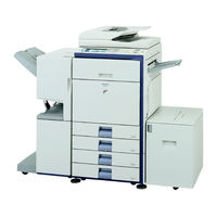
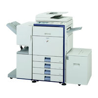
User Manuals: Sharp MX-2700 G Multifunction Printer
Manuals and User Guides for Sharp MX-2700 G Multifunction Printer. We have
2
Sharp MX-2700 G Multifunction Printer manuals available for free PDF download: Service Manual, Installation Manual
Sharp MX-2700 G Service Manual (429 pages)
DIGITAL FULL COLOR MULTIFUNCTIONAL SYSTEM
Brand:
Sharp
| Category:
Copier
| Size: 62.1 MB
Table of Contents
Contents
1
Table of Contents
2
Note for Installing Site
3
Precautions for Servicing
3
Warning for Servicing
3
Environmental Features
5
Product Features
5
Product Outline
5
Configuration
6
Lineup (Main Unit and Option)
6
Combination of Options List
7
Machine Configuration
7
Basic Specifications
8
Functional Specifications
12
Specifications of Copy Functions
12
Image Send Function
14
Others
16
PC-Fax Functions
16
PC-Fax/Pc-Internet Fax Operating Environment
16
Printer Function
17
Remote PC Functions (Network TWAIN)
17
Windows Driver Function
19
Document Filing Function
22
Ambient Conditions
23
Ambient Conditions for Transporting
23
Operating Environmental Conditions
23
Standard Environmental Conditions (Supply)
23
Consumable Parts
24
Supply System Table
24
Maintenance Parts List
26
Developer
27
Drum Cartridge
27
Production Number Identification
27
Toner Cartridge
27
External View and Internal Structure
28
Identification of each Section and Functions
28
Auto Document Feeder and Document Cover
30
Connectors
31
Operation Panel
32
Print and Send Status (Job Status)
33
Sensors
34
Switches
35
Clutches and Solenoids
36
Drive Motors
37
Lamps
38
Fans and Filters
39
Pwb
40
Fuses/Thermostats
41
Adjustment Volumes
42
Gate
42
Rollers
43
Adjustment Item List
45
Details of Adjustment
46
Developing Doctor Gap Adjustment
46
Developing Roller Main Pole Position Adjustment
47
Toner Density Reference Control Level Setting
47
High Voltage Adjustments
48
Main Charger Grid Voltage Adjustment
48
Developing Bias Voltage Adjustment
49
Transfer Voltage Adjustment
51
Color Image Density Sensor Calibration
52
Image Density Sensor, Image Registration Sensor Adjustment
52
Color Image Density Sensor, Black Image Density Sensor, Image Registration Sensor Adjustment
53
Image Skew Adjustment (LSU Unit)
54
OPC Drum Phase Adjustment
55
OPC Drum Phase Adjustment (Auto Adjustment)
56
Print Engine Image Magnification Ratio Adjustment (BK)
57
Engine Section
58
Image Off-Center Adjustment
58
Image Registration Adjustment
59
Scan Image Distortion Adjustment
65
Scanner (Reading) Unit Parallelism Adjustment
65
Scan Image (Sub Scanning Direction) Distortion Adjustment
66
Scan Image (Main Scanning Direction) Distortion Adjustment
67
Scan Image Focus Adjustment (CCD Unit Position Adjustment)
68
Scan Image Magnification Ratio Adjustment
69
Scan Image Skew Adjustment (RSPF)
69
Scan Image Magnification Ratio Adjustment (RSPF Mode)
70
Print Area (Void Area) Adjustment
71
Scan Image Off-Center
71
Scan Image Off-Center (RSPF Mode)
71
Scan Image Off-Center Adjustment
71
Copy Image Position, Image Loss Adjustment
72
Copy Color Balance/Density Adjustment
74
Print Lead Edge Image Position Adjustment (Printer Mode) (Print Engine Section)
74
Flowchart of the Copy Color Balance/Density Adjustment Procedures
76
CCD Gamma Adjustment (CCD Calibration)
78
Copy Color Balance Adjustment
79
Copy Density Adjustment
85
Copy Color Balance Adjustment (Color Balance Adjustment at each Density Level in each Color Copy Mode) (Normally Not Required)
86
Copy Density Adjustment (each Monochrome Copy Mode) (Whole Adjustment)
86
Monochrome Copy Density Adjustment
87
Gamma/Density Adjustment in the Text
88
Auto Color Balance Adjustment by the User
89
Background Process Condition Setting in the Color Auto Copy Mode
89
Color Document Identification Level
91
Printer Color Balance/Density Adjustment
92
Flow of Printer Color Balance/Density Adjustment Procedures
93
Printer Color Balance Adjustment
95
Printer Color Balance Adjustment (Manual)
97
Document Size Sensor Adjustment
102
Document Size Sensor Detection Point Adjustment
102
Fusing Paper Guide Position Adjustment
102
Document Size Sensor Sensitivity Adjustment
103
Manual Paper Feed Tray Paper Size (Width) Sensor Adjustment
103
RSPF Tray Paper Size (Width) Sensor Adjustment
104
Touch Panel Coordinate Setting Image Loss, Void Area, Image Off-Center, Image Magnification Ratio Auto Adjustment with SIM50-28
104
Image Off-Center Automatic Adjustment
105
Print Image Main Scanning Direction Image Magnification Ratio Automatic Adjustment
105
Copy Lead Edge Image Reference Position Adjustment, Image Off-Center, Sub Scanning Direction Image Magnification Ratio Automatic Adjustment
106
SPF Mode Image Off-Center, Image Lead Edge Position, Sub Scanning Direction Image Magnification Ratio Automatic Adjustment
106
Simulation
107
Starting the Simulation
107
Basic Operation Flowchart
108
List of Simulation Codes
109
Details of Simulation
115
Paper JAM Code
126
Detailed Descriptions of Print Pattern at Item a
227
Self Diag and Trouble Code
240
Self Diag Message Kinds
240
Self Diag Operation and Related Work Flow
240
Breakdown Mode List
241
Breakdown Sequence
241
Power on Trouble Detection Sequence
243
Trouble Code List
243
A0-01 PCU ROM Abnormality
247
A0-02 SCU ROM Abnormality
247
A0-10 Controller ROM Error
247
Details of Trouble Code
247
CE-04 FTP Server Account Name or Authentication Password Input Error
248
CE-05 FTP Server Directory Input Error
248
CE-06 POP3 Server Access Error
248
CE-07 POP3 Server Authentication Check Error
248
E7-01 System Data Trouble
249
E7-03 HDD Trouble
249
E7-05 Local Memory Access Error
249
E7-06 Decode Error Trouble: Compression Decode Error (a Compression File Can- Not Decompressed.)
249
LSU BD Detection Trouble
250
SCAN-ASIC Trouble
250
Shading Trouble (Black Correction)
250
Shading Trouble (White Correction)
250
Controller Connection Trouble
251
Controller Connection Trouble (Engine Detection)
251
Engine Connection Trouble
251
PWB Information Sum Error (Engine Detection)
251
E7-90 Communication Trouble between the Controller and the Engine
252
EE-EC Auto Developer Adjustment Trouble
252
EE-EL Auto Developer Adjustment Trouble
252
EE-EU Auto Development Adjustment Trouble
252
F1-11 Finisher Bundle Process Motor Abnormality
253
F1-15 Finisher Tray Lift Motor Abnormality
253
F1-19 Finisher Pre-Alignment Motor Abnormality
253
F1-20 Finisher After-Alignment Motor Abnormality
253
Finisher Backup RAM Trouble
254
Finisher Punch Backup RAM Trouble
254
Finisher Punch Registration Sensor Trouble (MX-FNX2)
254
Process Thermistor Trouble
254
Black Exclusive Image Density Sensor Trouble (Transfer Belt Surface Reflection Ratio Abnormality)
255
LSU Thermistor Trouble
255
Toner Empty Sensor Abnormality (MAGENTA)
255
Toner Empty Sensor Abnormality (YELLOW)
255
CL Phase Sensor Sensing Trouble
256
Process Humidity Sensor Trouble
256
Toner Supply Abnormality (BLACK)
256
Toner Supply Abnormality (CYAN)
256
Toner Cartridge CRUM Error (BLACK)
257
Toner Cartridge Improper Cartridge Detection (CYAN)
257
Toner Cartridge Improper Cartridge Detection (MAGENTA)
257
Toner Cartridge Improper Cartridge Detection (YELLOW)
257
Half Tone Process Control 1St Patch Reference Value Trouble (BLACK)
258
Half Tone Process Control 1St Patch Reference Value Trouble (CYAN)
258
Half Tone Process Control 1St Patch Reference Value Trouble (MAGENTA)
258
Registration Exclusive Image Density Sensor Trouble (Transfer Belt Surface Reflection Ratio Abnormality)
258
Half Tone Process Control 2Nd Patch Reference Value Trouble (CYAN)
259
Half Tone Process Control 2Nd Patch Reference Value Trouble (MAGENTA)
259
Half Tone Process Control 2Nd Patch Reference Value Trouble (YELLOW)
259
High-Density Process Control Density Correction Error (CYAN)
259
Lower Thermistor Open (TH_LM)
260
Main Unit Tray 2 Lift-Up Trouble
260
Non-Contact Thermistor Detection Thermistor Open (TH_UM_AD2)
260
Sub Thermistor Open (TH_US)
260
Fusing Section Low Temperature Trouble (TH_LM)
261
Fusing Section Low Temperature Trouble (TH_UM_AD2)
261
Mirror Feed Trouble
261
Sub Thermistor Fusing Section Low Temperature Trouble (TH_US)
261
Controller Fan/Hdd Fan Motor Trouble
262
Developing Motor Trouble (BLACK)
262
Developing Motor Trouble (COLOR)
262
Shift Motor Trouble
262
Full Wave Signal Width Abnormality
263
No Full Wave Signal
263
Polygon Motor Lock Detection
263
Power Cooling Fan/Ozone Exhaust Fan Trouble
263
EEPROM Check Sum Error (MFP Detection)
264
Flash Memory User Authentication Counter Check Sum Error
264
MFPC Section SRAM Memory Individual Data Check Sum Error
264
SRAM Memory Check Sum Error
264
Adjustment Value Check Sum Error (SCU Detection)
265
EEPROM (PCU) Check Sum Error
265
EEPROM Read/Write Error (PCU Detection)
265
EEPROM Read/Write Error (SCU Detection)
265
Desk Transport Motor Trouble
266
LCC 24V Power Abnormality
266
LCC Communication Trouble
266
LCC Transport Motor Trouble
266
Adjustments
45
General
45
Maintenance
267
Maintenance System Table
267
Details of Maintenance
269
Drum Peripheral
269
Drum Life
270
Lsu
271
Developing Section
272
Transfer Section
273
Fusing Section
274
Optical Section
275
Filters
276
Paper Feed Section
277
Transport Section/Paper Exit Reverse Section
278
Drive Section
279
Fusing Unit Counter
280
Maintenance Timing Display
280
Other Related Items
280
Transfer Unit System Counters
280
Cases Where Version-Up Is Required
281
Notes for Version-Up
281
Rom Version-Up
281
Update Procedures and Kinds of Firmware
281
Firmware Download Using USB Device
282
Firmware Download Using FTP
283
Firmware Download Using the Web Page
283
Block Diagram
285
Electrical Section
285
System Block Diagram
285
MFP Controller PWB
286
Pcu Pwb
287
Scanner Control PWB
288
Serial Communication
289
AC Power Line Diagram (100V Series)
290
AC Power Line Diagram (200V Series)
291
DC Power Line Diagram
292
Actual Wiring Chart
293
Power Supply Section (P1)
293
Front Section (P2)
294
Fusing Unit Section (P3)
295
High Voltage Section (P4)
296
Main Drive Unit Section
297
DL & DV Section (P7)
299
LSU Section (P8)
300
Paper Feed Unit Section (P9)
301
Paper Feed Drive Unit Section (P10)
302
PS Unit & Process Control Unit Section (P11)
303
Right Door Unit Section (P12)
304
Paper out Unit Section (P13)
305
PCU PWB-Other PWB (P14)
306
Desk & Lcc (P15)
307
Finisher & Coin Vendor (P16)
308
Scanner Section
309
FAX Section (P19)
311
MFP Board Section
312
Signal List
314
System Settings
318
System Settings (General) List
318
When User Authentication Is Enabled
318
Login by Login Name and Password
319
Login by User Number
319
System Settings (Administrator)
319
When User Authentication Is Not Enabled
319
JAM Cause Code List
323
Paper JAM Code
323
PCU JAM Cause
323
External Outfit
325
Disassembly and Assembly
325
Front Cabinet Upper
326
Right Cabinet Front
326
Upper Cabinet Rear
326
Upper Cabinet Right
326
Frame Cover
327
Operation Panel Base Plate
327
Paper Exit Tray Cabinet
327
Electrical and Mechanism Relation Diagram
328
Operational Descriptions
329
Outline
329
C] Scanner Section
331
Image Scan/Color Separation
332
Image Signal A/D Conversion
332
Operational Descriptions
332
Optical Section Drive
332
Scanner Lamp Drive
332
Maintenance
333
Maintenance
337
Manual Paper Feed Section
338
E] Tray Paper Feed Section
345
Operational Descriptions
347
Disassembly and Assembly
348
Paper Feed Operation
347
Preliminary Operation before Paper Feed
347
Remaining Paper Detection
347
Remaining Paper Detection Method
347
Maintenance
352
F] Paper Transport Section
353
Operational Descriptions
354
Maintenance
356
G] Duplex Section
357
Operational Descriptions
358
Maintenance
362
H] Lsu Section
363
Operational Descriptions
364
I] PHOTOCONDUCTOR SECTION
368
OPC Drum Section
369
Operational Descriptions
369
Disassembly and Assembly
370
Process Drum Unit
370
J] Toner Supply Section
375
Operational Descriptions
376
Maintenance
377
K] Developing Section
378
Operational Descriptions
379
Maintenance
382
L] Transfer Section
383
Operational Descriptions
384
Primary (Intermediate) Transfer Roller Separation Mechanism and Content
384
Disassembly and Assembly
385
Primary Transfer
385
Primary Transfer Unit
385
Secondary Transfer
389
Secondary Transfer Unit
389
Maintenance
391
Process Control Sensor, Registration Sensor Section
392
N] Fusing Section
395
Fusing Operation
396
Fusing Temperature Control
396
Fusing Unit Drive
396
Heater Lamp Drive
396
Operational Descriptions
396
Disassembly and Assembly
397
Maintenance
401
O] Paper Exit Section
402
Operational Descriptions
403
Maintenance
406
Main Drive Section
407
Maintenance
412
Q] Pwb Section
413
R] Fan and Filter Section
419
Maintenance
421
S] Sensor, Switch Section
422
Dehumidifier Heater Switch
423
Front Door Open/Close Switch
423
Right Door Open/Close Switch
423
Lead-Free Solder
426
Advertisement
Sharp MX-2700 G Installation Manual (88 pages)
DIGITAL FULL COLOR MULTIFUNCTIONAL SYSTEM
Brand:
Sharp
| Category:
All in One Printer
| Size: 15.26 MB
Table of Contents
Table of Contents
1
Sharp Corporation
1
MX-TRX1 (Exit Tray Unit)
2
MX-RPX1 (Reversing Single Pass Feeder)
2
Transit and Delivery
5
Auto Adjustment
16
MX-LCX1 (Large Capacity Tray)
32
MX-Fnx1
41
MX-Pnx1A/B/C/D
46
MX-Rbx1, MX-Fnx2
50
MX-PBX1 (Printer Expansion Kit)
64
MX-FRX1, MX-FRX1U (Data Security Kit)
66
Operation Check
68
MX-PKX1 (PS3 Expansion Kit)
70
AR-PF1 (Barcode Font Kit)
71
Scanner Function
73
MX-NSX1 (Network Scanner Expansion Kit)
73
MX-AMX1 (Application Integration Module)
74
MX-AMX2 (Application Communication Module)
76
MX-AMX3 (External Account Module)
77
Main Unit
78
MX-FXX1 (Facsimile Expansion Kit)
78
MX-FWX1 (Internet Fax Expansion Kit)
82
MX-SMX1 (256MB Expansion Memory Board)
83
Advertisement
Related Products
Sharp MX-2300G
Sharp MX-2700G
Sharp MX-2300 G
Sharp MX-6200N
Sharp MX-7000N
Sharp MX-M283
Sharp MX-M363
Sharp MX-M503
Sharp MX-M503N
Sharp MX-M453N
Sharp Categories
Microwave Oven
LCD TV
TV
Stereo System
All in One Printer
More Sharp Manuals
Login
Sign In
OR
Sign in with Facebook
Sign in with Google
Upload manual
Upload from disk
Upload from URL