Sign In
Upload
Manuals
Brands
Panasonic Manuals
Engine
MHME502G1
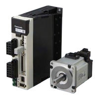
Panasonic MHME502G1 AC Servo Motor Manuals
Manuals and User Guides for Panasonic MHME502G1 AC Servo Motor. We have
1
Panasonic MHME502G1 AC Servo Motor manual available for free PDF download: Operating Instructions Manual
panasonic MHME502G1 Operating Instructions Manual (394 pages)
MINAS A5-series AC Servo motor and driver
Brand:
panasonic
| Category:
Engine
| Size: 12.38 MB
Table of Contents
4. Setup
5
When in Trouble
3
Table of Contents
5
Safety Precautions
6
1 1 . before Using the Products
13
1 Introduction
14
Outline
14
On Opening the Product Package
14
Motor
14
2 Driver
15
Check of the Model
15
Parts Description (a to E-Frame)
17
Specifications
18
Block Diagram
20
3 Motor
22
Check of the Model
22
Parts Description
24
4 Check of the Combination of the Driver and the Motor
25
Incremental Specifications, 20-Bit
27
Absolute Specifications, 17-Bit
27
Junction Cable for Motor
31
5 Installation
32
Motor
32
6 Permissible Load at Output Shaft
35
Motor
35
2 1 . Preparation
37
1 Conformance To International Standards
38
EC Directives
38
Composition of Peripheral Equipments
40
2 System Configuration And Wiring
42
Driver and List of Applicable Peripheral Equipments
42
Overall Wiring (Connector Type)
44
Wiring of the Main Circuit (Connector Type)
45
Wiring Diagram (Connector Type)
48
Overall Wiring (Terminal Block Type)
50
Wiring of the Main Circuit (Terminal Block Type)
51
Wiring Diagram (Terminal Block Type)
53
Specifications of Motor Connector
54
Wiring Method to Connector
55
3 Wiring To The Connector, X1
56
Connecting Host Computer
56
4 Wiring To The Connector, X2
56
Connecting Communication Connector
56
5 Wiring To The Connector, X3
58
Safety Function Connector
58
6 Wiring To The Connector, X4
59
Connection to Host Controller
59
7 Wiring To The Connector, X5
60
Connect on to External Scale
60
8 Wiring To The Connector, X6
62
Connection to Encoder
62
9 Wiring To The Connector, X7
65
Monitor Output
65
10 Timing Chart
66
Timing on Power-Up
66
Alarm
67
Servo-Lock
68
Servo-ON/OFF
69
11 Built-In Holding Brake
70
Outline
70
Specifications
71
12 Dynamic Brake
72
Condition Setting Chart
74
13 Setup Of Parameter And Mode
75
Outline / Setup / Connection
75
Composition and List of Parameters
76
List of Parameters
77
Setup of Torque Limit
85
14 Setup of Command Division and Multiplication Ratio (Electronic Gear Ratio)
86
Relation between Electronic Gear and Position Resolution or Traveling Speed
86
15 How To Use The Front Panel
88
Setup
89
Structure of each Mode
90
Setup of Front Panel Lock
92
Monitor Mode SELECTION Display
93
Monitor Mode (EXECUTION Display)
96
Parameter Setup Mode
108
EEPROM Writing
109
Auxiliary Function Mode SELECTION Display
110
Auxiliary Function Mode (EXECUTION Display)
111
3 . Connection 1
119
Connection
120
1 Outline of Mode Position Control Mode
120
Velocity Control Mode
124
Torque Control Mode
127
Full-Closed Control Mode
130
2 Control Block Diagram
132
Position Control Mode
132
Velocity Control Mode
133
Torque Control Mode
134
Full-Closed Control Mode
135
3 Wiring Diagram To The Connector, X4
136
Example of Control Mode Specific Wiring
136
Connecting Example to Host Controller
138
4 Inputs And Outputs On Connector X4
148
Interface Circuit (Input)
148
Interface Circuit (Output)
150
Input Signal and Pin no
153
4 1 . Setup 2
169
Details Of Parameter
170
List of Parameters
171
[Class 0] Basic Setting
172
Adjustment
180
Gain Adjustment
181
[Class 1] Gain Adjustment
182
[Class 2] Damping Control
187
[Class 3] Verocity/ Torque/ Full-Closed Control
192
[Class 4] I/F Monitor Setting
201
[Class 5] Enhancing Setting
211
[Class 6] Special Setting
225
Trial Run (Jog Run)
226
Inspection before Trial Run
226
Trial Run by Connecting the Connector, CN X4
227
Setup of Motor Rotational Speed and Input Pulse Frequency
230
5 1 . Adjustment
231
1 Gain Adjustment
232
Outline
232
2 Real-Time Auto-Gain Tuning Basic
234
3 Adaptive Filter Adaptive Filter
240
4 Manual Gain Tuning (Basic) Outline
243
Adjustment in Position Control Mode
244
Adjustment in Velocity Control Mode
245
Adjustment in Torque Control Mode
245
Adjustment in Full-Closed Control Mode
246
Gain Switching Function
247
Suppression of Machine Resonance
251
5 Manual Gain Tuning (Application) Damping Control
254
Feed Forward Function
256
Instantaneous Speed Observer
258
Disturbance Observer
260
3Rd Gain Switching Function
262
Friction Torque Compensation
264
Inertia Ratio Switching Function
266
Hybrid Vibration Damping Function
268
6 About Homing Operation
269
Press & Hold Control
271
6 . When in Trouble 1
273
When in Trouble
273
When in Trouble What to Check
274
Protective Function (What Is Error Code ?)
276
Protective Function (Detail of Error Code)
278
1 When in Trouble
274
2 Setup of Gain Pre-Adjustment Protection
287
3 Troubleshooting
290
Motor Does Not Run
290
Unstable Rotation (Not Smooth), Motor Runs Slowly Even with Speed Zero at Velocity Control Mode
292
Positioning Accuracy Is Poor
293
Origin Point Slips
294
Abnormal Motor Noise or Vibration
294
Overshoot/Undershoot, Overheating of the Motor (Motor Burn-Out)
295
Motor Speed Does Not Reach to the Setup
295
Motor Revolutions (Travel) Is too Large or Small
295
7 1 . Supplement
297
Supplement
297
Timing Chart
302
Example of Connection
304
2 Absolute System
306
Configuration
307
Battery (for Backup) Installation
309
Setup (Initialization) of Absolute Encoder
312
Transferring Absolute Data
312
Transferring External Scale Absolute Data
317
Outline Of Setup Support Software, "Panaterm
322
Setup on the PC
322
4 Communication
323
Specifications
326
7 4. Communication 1 List of Communication Command Supplement
335
Communication
336
Details of Communication Command
336
Command Mode
336
Read out of CPU Version
336
Read out of Driver Model
336
Read out of Motor Model
336
Capture and Release of Execution Right
337
Setup of RS232 Protocol Parameter
337
Setup of RS485 Protocol Parameter
337
Read out of Status
338
Read out of Command Pulse Counter
338
Read out of Feedback Pulse Counter
339
Read out of Present Speed
339
Read out of Present Torque Output
339
Read out of Present Deviation Counter
340
Read out of Input Signal
340
Read out of Output Signal
341
Read out of Present Speed, Torque and Deviation Counter
342
A Read out of Status, Input Signal and Output Signal
342
D Read out of Absolute Encoder
344
E Read out of External Scale Deviation and Sum of Pulses
344
Individual Read out of Parameter
345
Individual Writing of Parameter
345
Writing of Parameter to EEPROM
345
Individual Read out of User Parameter
346
Read out of Two or more User Parameter
347
Writing of Two or more User Parameter
348
Read out of Present Alarm Data
348
Batch Read out of Alarm History
349
Alarm Clear
349
B Absolute Clear
350
5 Motor Characteristics (S-T Characteristics)
352
Dimensions
359
Motor
363
6 Dimensions
363
Motor
364
7 Options
368
Noise Filter
368
Surge Absorber
370
Noise Filter for Signal Lines
371
Junction Cable for Encoder
372
Junction Cable for Motor (Without Brake)
374
Junction Cable for Motor (with Brake)
376
Junction Cable for Brake
378
Connector Kit
379
Battery for Absolute Encoder
385
Mounting Bracket
386
Reactor
387
External Regenerative Resistor
389
Warranty
392
Cautions for Proper Use
393
Advertisement
Advertisement
Related Products
Panasonic MHME102G1
Panasonic MHME152G1
Panasonic MHME202G1
Panasonic MHME302G1
Panasonic MHME402G1
Panasonic MBDHT2110
Panasonic M7RX15GB4L
Panasonic M9RX40GV4Y
Panasonic M9RX40GBV4Y
Panasonic M9RZ60GV4Y
Panasonic Categories
Camcorder
Air Conditioner
TV
Digital Camera
Cordless Telephone
More Panasonic Manuals
Login
Sign In
OR
Sign in with Facebook
Sign in with Google
Upload manual
Upload from disk
Upload from URL