Sign In
Upload
Manuals
Brands
Motorola Manuals
Two-Way Radio
Professional GP680
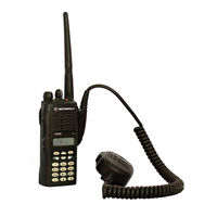
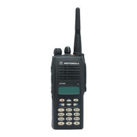
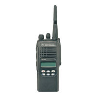
Motorola Professional GP680 Manuals
Manuals and User Guides for Motorola Professional GP680. We have
11
Motorola Professional GP680 manuals available for free PDF download: Service Manual, Service Information, User Manual
Motorola Professional GP680 Service Manual (290 pages)
Brand:
Motorola
| Category:
Two-Way Radio
| Size: 7.03 MB
Table of Contents
Table of Contents
15
Safety Information
5
Rf Exposure Compliance and Control Guidelines and Operating Instructions
6
Medical Devices
8
Blasting Caps and Areas
9
Operational Cautions
9
Operational Warnings
9
Potentially Explosive Atmospheres
9
Intrinsically Safe Radio Information
10
Chapter 1 MODEL CHART and TECHNICAL SPECIFICATIONS
17
GP340 Model Chart
17
GP640 / GP680 Model Chart
17
Technical Specifications
18
Chapter 2 THEORY of OPERATION
21
Introduction
21
Transmitter
21
Power Amplifier
21
Antenna Matching Network
22
Antenna Switch
22
Harmonic Filter
22
Power Control Integrated Circuit (PCIC)
22
Receiver
23
Receiver Front-End
23
Receiver Back-End
24
Automatic Gain Control Circuit
25
Frequency Generation Circuitry
26
Synthesizer
26
Voltage Controlled Oscillator (VCO)
28
Chapter 3 TROUBLESHOOTING CHARTS
31
Troubleshooting Flow Chart for Receiver (Sheet 1 of 2)
31
Troubleshooting Flow Chart for Receiver (Sheet 2 of 2)
32
Troubleshooting Flow Chart for Transmitter
33
Troubleshooting Flow Chart for Synthesizer
34
Troubleshooting Flow Chart for VCO
35
Pcb/Schematics/Parts Lists
37
Chapter 4 PCB/SCHEMATICS/PARTS LISTS
39
PCB 8485726Z01 - Schematics
39
Pcb : 8485726Z01
39
PCB 8485726Z01 - Parts List
47
PCB 8485726Z04 - Schematics
50
Pcb : 8485726Z04
50
PCB 8485726Z04 - Parts List
58
Table of Contents
63
Chapter 1 INTRODUCTION
65
Scope of Manual
65
Warranty and Service Support
65
After Warranty Period
65
Warranty Period and Return Instructions
65
European Radio Support Centre (ERSC)
66
Piece Parts
66
Related Documents
67
Technical Support
67
Radio Model Information
68
Chapter 2 MAINTENANCE
69
Introduction
69
Preventive Maintenance
69
Cleaning
69
Inspection
69
Safe Handling of CMOS and LDMOS
70
General Repair Procedures and Techniques
70
Notes for All Schematics and Circuit Boards
73
Chapter 3 SERVICE AIDS
75
Recommended Test Tools
75
Recommended Test Equipment
77
Table of Contents
81
Keypad and Flexible Connectors
83
Keypad
83
Flexible Connectors
83
Troubleshooting Chart
84
Allocation of Schematics and Circuit Boards
85
Flexible Connectors
85
Keypad Pcbs
85
Pcb/Schematic Diagrams and Parts List: Flexes
87
Keypad - Controller Flex
87
Universal Connector Flex
88
Pcb/Schematic Diagrams and Parts List: Keypad
89
PCB 8480574Z06 - Diagram
89
PCB 8480574Z06 - Parts List
91
PCB 8480682Z04 - Diagrams
92
PCB 8480682Z04 - Parts List
94
Table of Contents
97
Overview
99
Radio Power Distribution
99
Controller Circuits
100
Controller Architecture
100
MCU Digital Architecture
100
Real Time Clock
101
Modb/Vstby Supply
102
Audio/Signaling Architecture
102
300R1 Controller
103
VHF Controller (for Models with PCB 8486473Z04)
105
Lowband Controller
106
Allocation of Schematics and Circuit Boards
107
Controller - Set 1 (PCB 8486062B12/B14, 8485726Z01)
111
Controller - Set 2 (PCB 8486101B09/B10)
117
Controller - Set 3 (PCB 8485658Z01)
123
Controller - Set 4 (PCB 8486062B16/17, 8486101B11)
129
Controller - Set 5 (PCB 8485726Z04)
135
Controller - Set 6 (PCB 8486473Z04)
141
Table of Contents
149
Chapter 1 MODEL CHART and TECHNICAL SPECIFICATIONS
151
GP320/GP340/GP360/GP380 Model Chart
151
GP140 Model Chart
152
GP640/GP680 Model Chart
152
GP1280 Model Chart
153
GP240/GP280/GP540/GP580 Model Chart
154
Technical Specifications
155
Chapter 2 THEORY of OPERATION
157
Introduction
157
VHF Transmitter
157
Power Amplifier
157
Antenna Matching Network
158
Antenna Switch
158
Harmonic Filter
158
Power Control Integrated Circuit (PCIC)
158
VHF Receiver (for All Models Except those with PCB8486473Z04)
159
Receiver Front-End
159
Receiver Back End
160
Receiver Back-End
160
Automatic Gain Control (AGC)
161
Receiver Front-End
162
Receiver Back End
163
Receiver Back-End
163
Automatic Gain Control (AGC)
164
Frequency Generation Circuit
164
Synthesizer
165
Voltage Controlled Oscillator
166
Voltage Controlled Oscillator (VCO)
166
Voice Storage (GP1280)
168
Chapter 3 TROUBLESHOOTING CHARTS
171
Troubleshooting Flow Chart for Receiver for All Models Except those with PCB 8486473Z04
172
Troubleshooting Flow Chart for Receiver for Models with PCB 8486473Z04
174
Troubleshooting Flow Chart for Transmitter
175
Troubleshooting Flow Chart for Synthesizer
176
Troubleshooting Flow Chart for VCO
177
Troubleshooting Flow Chart for Receive Message/Personal Memo Recording
178
Troubleshooting Flow Chart for Message Playback
179
Controls and Switches
181
Receiver Front End
181
Synthesizer
181
Allocation of Schematics and Circuit Boards
181
Voice Storage Facility
181
Controls and Switches
182
Receiver Front End
182
Transmitter
182
VHF PCB 8486062B12 / Schematics
185
VHF PCB 8486062B12 Parts List
193
VHF PCB 8486101B09 / Schematics (GP1280)
197
VHF PCB 8086101B09 Parts List (GP1280)
201
Vhf Pcb 8486062B14
205
VHF PCB 8486062B14 Parts List
207
Vhf Pcb 8486101B10
211
VHF PCB 8486101B10 Parts List (GP1280)
213
Vhf Pcb 8486062B16
217
11.0 VHF PCB 8486062B16 Parts List
225
13.0 Vhf Pcb 8486062B17
231
Vhf Pcb 8486101B11
235
15.0 VHF PCB 8486101B11 Parts List
237
Vhf Pcb 8486473Z04
241
Table of Contents
257
Chapter 1 MODEL CHART and TECHNICAL SPECIFICATIONS
259
GP340/GP380 Model Chart
259
Technical Specifications
260
Chapter 2 THEORY of OPERATION
263
Lowband Transmitter
263
Power Amplifier (PA)
263
Antenna Matching Network
264
Antenna Switch
264
Harmonic Filter
264
Power Control Integrated Circuit (PCIC)
264
Temperature Cut Back Circuit
264
Lowband Receiver
265
Receiver Front-End
265
Automatic Gain Control (AGC)
266
Receiver Back-End
266
Frequency Generation Circuit
267
Synthesizer
268
Buffer
269
Diplexer and Output Filters
269
Prescalar Feedback
269
Receive VCO
269
Transmit VCO
269
Chapter 3 TROUBLESHOOTING CHARTS
271
Receiver (Sheet 1 of 2)
271
Receiver (Sheet 2 of 2)
272
Transmitter
273
Synthesizer
274
Voltage Controlled Oscillator
275
Main Board Bottom Side
277
Main Board Top Side
277
Parts List
277
Allocation of Schematics and Circuit Boards
277
Controller Circuits
277
PCB 8485658Z03 - Schematics
279
PCB 8485658Z03 - Parts List
288
Advertisement
Motorola Professional GP680 Service Information (108 pages)
Professional Radio, VHF 136-174MHz
Brand:
Motorola
| Category:
Radio
| Size: 4.06 MB
Table of Contents
Table of Contents
3
Chapter 1 MODEL CHART and TECHNICAL SPECIFICATIONS
5
GP320/GP340/GP360/GP380 Model Chart
5
GP140 Model Chart
6
GP640/GP680 Model Chart
6
GP1280 Model Chart
7
GP240/GP280/GP540/GP580 Model Chart
8
Technical Specifications
9
Chapter 2 THEORY of OPERATION
11
Introduction
11
VHF Transmitter
11
Power Amplifier
11
Antenna Switch
12
Harmonic Filter
12
Antenna Matching Network
12
Power Control Integrated Circuit (PCIC)
12
VHF Receiver (for All Models Except those with PCB8486473Z04)
13
Receiver Front-End
13
Receiver Back-End
14
Automatic Gain Control (AGC)
15
Receiver Front-End
16
Receiver Back-End
17
Automatic Gain Control (AGC)
18
Frequency Generation Circuit
18
Synthesizer
19
Voltage Controlled Oscillator (VCO)
20
Voice Storage (GP1280)
22
Chapter 3 TROUBLESHOOTING CHARTS
25
Troubleshooting Flow Chart for Receiver for All Models Except those with PCB 8486473Z04
26
Troubleshooting Flow Chart for Receiver for Models with PCB 8486473Z04
28
Troubleshooting Flow Chart for Transmitter
29
Troubleshooting Flow Chart for Synthesizer
30
Troubleshooting Flow Chart for VCO
31
Troubleshooting Flow Chart for Receive Message/Personal Memo Recording
32
Troubleshooting Flow Chart for Message Playback
33
Chapter 4 VHF PCB/SCHEMATICS/PARTS LISTS
39
VHF PCB 8486062B12 / Schematics
39
VHF PCB 8486062B12 Parts List
47
VHF PCB 8486101B09 / Schematics (GP1280)
51
VHF PCB 8086101B09 Parts List (GP1280)
55
Vhf Pcb 8486062B14
59
VHF PCB 8486062B14 Parts List
61
Vhf Pcb 8486101B10
65
VHF PCB 8486101B10 Parts List (GP1280)
67
Vhf Pcb 8486062B16
71
11.0 VHF PCB 8486062B16 Parts List
79
13.0 Vhf Pcb 8486062B17
85
Vhf Pcb 8486101B11
89
15.0 VHF PCB 8486101B11 Parts List
91
Vhf Pcb 8486473Z04
95
Motorola Professional GP680 User Manual (62 pages)
Professional Radio
Brand:
Motorola
| Category:
Two-Way Radio
| Size: 2.35 MB
Table of Contents
Table of Contents
3
Radio Overview
5
Operation and Control Functions
5
Radio Controls
5
Programmable Buttons
6
Menu Keys
8
Menu Navigation Chart
9
Keypad Keys
10
Keypad / Character Table
11
LCD Display and Icons
12
Audio Signal Tones
13
Getting Started
15
Battery Information
15
Battery Care and Tips
15
Recycling or Disposal of Batteries
16
Charging the Battery
16
Accessory Information
18
Attaching the Battery
18
Removing the Battery
18
Attaching the Antenna
19
Removing the Antenna
19
Attaching the Belt Clip
20
Removing the Belt Clip
20
Attaching the Side Connector
21
Radio Operation
22
Turning the Radio On-Off
22
Adjusting the Radio's Volume
22
Radio Registration
22
Radio Calls
23
Making a Call
23
Contact List
23
User Absent
27
Dedicated Calls
28
Manual Dialling
28
Last Number Redial
29
Keypad Edit
29
Ending a Call
30
Cancelling a Call
30
Receiving a Call
31
Receiving a Call on a OACSU System
31
Receiving a Call on a FOACSU System
31
Missed Calls
32
Call Diversion
35
Special Calls
37
Short Data Messages (SDM)
37
Receiving an SDM
37
Making an SDM
40
Status Calls
42
Making a Status Call
42
Receiving a Status Call
43
Emergency Calls
44
Priority Calls
45
Broadcast Calls
45
Dtmf
46
Personality
47
Mpt
47
Talkgroup
47
Fixed and Dynamic Groups
47
Conventional Mode
48
Personality Selection
49
Features
51
Voice Storage
51
Voice Recorder
51
Voice Message
54
Call Progress
56
Call Progress - Sending
56
Call Progress - Receiving
57
Call Progress - Cancelling
58
Call Progress - Ending
58
Safety Information
59
Safe and Efficient Operation
59
Exposure to Radio Frequency Energy
59
Radio Operation and EME Exposure
60
Electromagnetic Interference/Compatibility
60
Operational Warnings
60
Vehicles with an Air Bag
60
Potentially Explosive Atmospheres
60
Batteries
60
Blasting Caps and Areas
61
Operational Cautions
61
Damaged Antennas
61
Batteries
61
General Radio Care
61
Advertisement
Motorola Professional GP680 Service Information (52 pages)
Professional Radio GP Series; Power Distribution and Controller Information
Brand:
Motorola
| Category:
Radio
| Size: 0.83 MB
Table of Contents
English
3
Computer Software Copyrights
2
Table of Contents
3
Chapter 1 THEORY of OPERATION
5
Overview
5
Radio Power Distribution
5
Controller Circuits
6
Controller Architecture
6
MCU Digital Architecture
6
Real Time Clock
7
Modb/Vstby Supply
8
Audio/Signaling Architecture
8
Chapter 2 Troubleshooting Charts
9
VHF Controller (for Models with PCB 8486473Z04)
11
Lowband Controller
12
300R1 Controller
9
Chapter 3 CONTROLLER SCHEMATICS
13
Allocation of Schematics and Circuit Boards
13
Unknown
14
Controller - Set 1 (PCB 8486062B12/B14, 8485726Z01)
17
Controller - Set 2 (PCB 8486101B09/B10)
23
Overall Controller Schematic
23
Controller - Set 3 (PCB 8485658Z01)
29
Overall Controller Schematic
29
Controller - Set 4 (PCB 8486062B16/17, 8486101B11)
35
Memory
35
Controller - Set 5 (PCB 8485726Z04)
41
Memory
41
Interface
41
Controller - Set 6 (PCB 8486473Z04)
47
Interface
47
Motorola Professional GP680 Service Information (32 pages)
GP Series
Brand:
Motorola
| Category:
Radio
| Size: 0.35 MB
Table of Contents
Computer Software Copyrights
2
Table of Contents
3
Chapter 1 MODEL CHART and TECHNICAL SPECIFICATIONS
5
GP320/GP340/GP360/GP380 Model Chart
5
GP140 Model Chart
6
GP640/GP680 Model Chart
6
GP1280 Model Chart
7
GP240/GP280/GP540/GP580 Model Chart
8
Technical Specifications
9
Chapter 2 THEORY of OPERATION
11
Introduction
11
UHF Transmitter
11
Power Amplifier
11
Antenna Switch
12
Harmonic Filter
12
Antenna Matching Network
12
Power Control Integrated Circuit (PCIC)
12
UHF Receiver
13
Receiver Front-End
13
Receiver Back-End
14
Automatic Gain Control (AGC)
15
Frequency Generation Circuit
16
Synthesizer
17
Voltage Controlled Oscillator (VCO)
18
Voice Storage (GP1280 Only)
20
Chapter 3 TROUBLESHOOTING CHARTS
23
Troubleshooting Flow Chart for Receiver (Sheet 1 of 2)
23
Troubleshooting Flow Chart for Receiver (Sheet 2 of 2)
24
Troubleshooting Flow Chart for Transmitter
25
Troubleshooting Flow Chart for Synthesizer
26
Troubleshooting Flow Chart for VCO
27
Allocation of Schematics and Circuit Boards
29
Motorola Professional GP680 Service Information (30 pages)
VHF (136-174MHz)
Brand:
Motorola
| Category:
Radio
| Size: 0.35 MB
Table of Contents
Computer Software Copyrights
2
Table of Contents
3
Chapter 1 MODEL CHART and TECHNICAL SPECIFICATIONS
5
GP320/GP340/GP360/GP380 Model Chart
5
GP140 Model Chart
6
GP640/GP680 Model Chart
6
GP1280 Model Chart
7
GP240/GP280/GP540/GP580 Model Chart
8
Technical Specifications
9
Chapter 2 THEORY of OPERATION
11
Introduction
11
VHF Transmitter
11
Power Amplifier
11
Antenna Switch
12
Harmonic Filter
12
Antenna Matching Network
12
Power Control Integrated Circuit (PCIC)
12
VHF Receiver
13
Receiver Front-End
13
Receiver Back-End
14
Automatic Gain Control (AGC)
15
Frequency Generation Circuit
16
Synthesizer
17
Voltage Controlled Oscillator (VCO)
18
Voice Storage (GP1280)
20
Chapter 3 TROUBLESHOOTING CHARTS
23
Troubleshooting Flow Chart for Receiver (Sheet 1 of 2)
23
Troubleshooting Flow Chart for Receiver (Sheet 2 of 2)
24
Troubleshooting Flow Chart for Transmitter
25
Troubleshooting Flow Chart for Synthesizer
26
Troubleshooting Flow Chart for VCO
27
Allocation of Schematics and Circuit Boards
29
Motorola Professional GP680 Service Information (28 pages)
GP600 Series
Brand:
Motorola
| Category:
Radio
| Size: 0.19 MB
Table of Contents
Computer Software Copyrights
2
Table of Contents
3
Chapter 1 MODEL CHART and TECHNICAL SPECIFICATIONS
5
GP640/GP680 Model Chart
5
GP1280 Model Chart
5
Technical Specifications
7
Chapter 2 THEORY of OPERATION
9
Introduction
9
UHF2 Transmitter
9
Power Amplifier
9
Antenna Switch
10
Harmonic Filter
10
Antenna Matching Network
10
Power Control Integrated Circuit (PCIC)
10
UHF2 Receiver
11
Receiver Front-End
11
Receiver Back-End
12
Automatic Gain Control (AGC)
13
Frequency Generation Circuit
14
Synthesizer
15
Voltage Control Oscillator (VCO)
16
Voice Storage (GP1280 Only)
18
Chapter 3 TROUBLESHOOTING CHARTS
21
Troubleshooting Flow Chart for Receiver (Sheet 1 of 2)
21
Troubleshooting Flow Chart for Receiver (Sheet 2 of 2)
22
Troubleshooting Flow Chart for Transmitter
23
Troubleshooting Flow Chart for Synthesizer
24
Troubleshooting Flow Chart for VCO
25
Chapter 4 UHF2 PCB/SCHEMATICS/PARTS LISTS
27
Allocation of Schematics and Circuit Boards
27
Motorola Professional GP680 Service Information (26 pages)
GP Series 300R1 (300 - 350MHz)
Brand:
Motorola
| Category:
Radio
| Size: 0.18 MB
Table of Contents
Computer Software Copyrights
2
Table of Contents
3
Chapter 1 MODEL CHART and TECHNICAL SPECIFICATIONS
5
GP340 Model Chart
5
GP640 / GP680 Model Chart
5
Technical Specifications
6
Chapter 2 THEORY of OPERATION
9
Introduction
9
Transmitter
9
Power Amplifier
9
Antenna Switch
10
Harmonic Filter
10
Antenna Matching Network
10
Power Control Integrated Circuit (PCIC)
10
Receiver
11
Receiver Front-End
11
Receiver Back-End
12
Automatic Gain Control Circuit
13
Frequency Generation Circuitry
14
Synthesizer
14
Voltage Controlled Oscillator (VCO)
16
Chapter 3 TROUBLESHOOTING CHARTS
19
Troubleshooting Flow Chart for Receiver (Sheet 1 of 2)
19
Troubleshooting Flow Chart for Receiver (Sheet 2 of 2)
20
Troubleshooting Flow Chart for Transmitter
21
Troubleshooting Flow Chart for Synthesizer
22
Troubleshooting Flow Chart for VCO
23
Chapter 4 PCB/SCHEMATICS/PARTS LISTS
25
Allocation of Schematics and Circuit Boards
25
Motorola Professional GP680 User Manual (18 pages)
Professional Radio
Brand:
Motorola
| Category:
Two-Way Radio
| Size: 1.79 MB
Table of Contents
Table of Contents
3
Contents
4
General Information
4
Operation and Control Functions
5
Radio Controls
5
Audio Signal Tones
6
Programmable Buttons
8
Menu Keys
8
Menu Navigation Chart
9
Keypad Keys
10
Keypad/Character Table
11
LCD Display and Icons
12
Getting Started
13
Radio On-Off/Volume Control
13
Radio Operation
13
Sending a Call
13
Receiving a Call
13
Cancelling a Call
14
Ending a Call
14
Battery Information
14
Battery Care and Tips
14
Recycling or Disposal of Batteries
15
Charging the Battery
15
Accessory Information
16
Attaching/Removing the Battery
16
Attaching/Removing the Belt Clip
16
Motorola Professional GP680 Service Information (43 pages)
Professional Radio
Brand:
Motorola
| Category:
Radio
| Size: 5.47 MB
Motorola Professional GP680 Service Information (30 pages)
Professional Radio, Power Distribution and Controller
Brand:
Motorola
| Category:
Two-Way Radio
| Size: 0.58 MB
Table of Contents
Table of Contents
3
Overview
5
Radio Power Distribution
5
Controller Circuits
6
Controller Architecture
6
MCU Digital Architecture
6
Real Time Clock
7
Modb/Vstby Supply
8
Audio/Signaling Architecture
8
All Models Except those with PCB 8486458Z03
9
Models with PCB 8486458Z03
10
Advertisement
Related Products
Motorola GP644
Motorola Professional GP640
MOTOROLA RADIUS GP300
Motorola GP338
Motorola GP328
Motorola GP380 Series
Motorola GP328 Plus
Motorola GP338 Plus
Motorola GP338 XLS
Motorola GP580 EX
Motorola Categories
Cell Phone
Two-Way Radio
Baby Monitor
Cordless Telephone
Radio
More Motorola Manuals
Login
Sign In
OR
Sign in with Facebook
Sign in with Google
Upload manual
Upload from disk
Upload from URL