Sign In
Upload
Manuals
Brands
Motorola Manuals
Controller
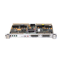
MVME172-233
Motorola MVME172-233 Manuals
Manuals and User Guides for Motorola MVME172-233. We have
1
Motorola MVME172-233 manual available for free PDF download: Programmer's Reference Manual
Motorola MVME172-233 Programmer's Reference Manual (354 pages)
VME Embedded Controller
Brand:
Motorola
| Category:
Controller
| Size: 3.34 MB
Table of Contents
Table of Contents
7
CHAPTER 1 Board Description and Memory Maps
19
Introduction
19
Overview
19
Table 1-1. MVME172 Features Summary
21
Requirements
22
Block Diagrams
23
Functional Description
23
No-Vmebus-Interface Option
23
Figure 1-1. 200/300-Series MVME172 Block Diagram
24
Figure 1-2. 400/500-Series MVME172 Block Diagram
25
Table 1-2. Redundant Functions in the Vmechip2 and MC2 Chip
26
Vmebus Interface and Vmechip2
27
Memory Maps
27
Local Bus Memory Map
27
Normal Address Range
27
Table 1-3. 200/300-Series MVME172 Local Bus Memory Map
28
Table 1-4. 400/500-Series MVME172 Local Bus Memory Map
30
Table 1-5. 200/300-Series MVME172 Local I/O Devices Memory Map
32
Table 1-6. 400/500-Series MVME172 Local I/O Devices Memory Map
33
Detailed I/O Memory Maps
39
Table 1-7. Vmechip2 Memory Map (Sheet 1 of 3)
40
Table 1-8. MC2 Chip Register Map
45
Table 1-9. IP2 Chip Overall Memory Map
46
Table 1-10. IP2 Chip Memory Map - Control and Status Registers
47
Table 1-11. MCECC Internal Register Memory Map
53
Table 1-12. Z85230 SCC Register Addresses
55
Table 1-13. 82596CA Ethernet LAN Memory Map
56
Table 1-14. 53C710 SCSI Memory Map
57
BBRAM/TOD Clock Memory Map
58
Table 1-15. MK48T58 BBRAM/TOD Clock Memory Map
58
Table 1-16. BBRAM Configuration Area Memory Map
59
Table 1-17. TOD Clock Memory Map
60
Interrupt Acknowledge Map
64
Vmebus Memory Map
64
Vmebus Accesses to the Local Bus
65
Vmebus Short I/O Memory Map
65
Software Support Considerations
65
Interrupts
65
Cache Coherency
66
Sources of Local BERR
66
Local Bus Time-Out
66
Vmebus Access Time-Out
67
Vmebus BERR
67
Local DRAM Parity Error
67
Vmechip2
67
Bus Error Processing
67
Description of Error Conditions on the MVME172
68
MPU Parity Error
68
MPU Off-Board Error
69
MPU TEA - Cause Unidentified
69
MPU Local Bus Time-Out
69
DMAC Vmebus Error
70
DMAC Parity Error
70
DMAC Off-Board Error
71
DMAC LTO Error
71
DMAC TEA - Cause Unidentified
72
LAN Parity Error
72
LAN Off-Board Error
73
LAN LTO Error
73
SCSI Parity Error
74
SCSI Off-Board Error
74
SCSI LTO Error
74
Example of the Proper Use of Bus Timers
75
MVME172 MC68060 Indivisible Cycles
76
Illegal Access to IP Modules from External Vmebus Masters
77
CHAPTER 2 Vmechip2
79
Introduction
79
Summary of Major Features
79
Functional Blocks
82
Local Bus to Vmebus Interface
82
Figure 2-1. Vmechip2 Block Diagram
83
Local Bus to Vmebus Requester
85
Vmebus to Local Bus Interface
87
Local Bus to Vmebus DMA Controller
88
No Address Increment DMA Transfers
90
DMAC Vmebus Requester
91
Tick and Watchdog Timers
92
Prescaler
92
Tick Timers
93
Watchdog Timer
93
Vmebus Interrupter
94
Vmebus System Controller
95
Arbiter
95
IACK Daisy-Chain Driver
95
Bus Timer
95
Reset Driver
96
Local Bus Interrupter and Interrupt Handler
96
Global Control and Status Registers
98
LCSR Programming Model
98
Table 2-1. Vmechip2 Memory Map - LCSR Summary (Sheet 1 of 2)
100
Programming the Vmebus Slave Map Decoders
104
Vmebus Slave Ending Address Register 1
106
Vmebus Slave Starting Address Register 1
106
Vmebus Slave Ending Address Register 2
107
Vmebus Slave Starting Address Register 2
107
Vmebus Slave Address Translation Address Offset Register 1
107
Vmebus Slave Address Translation Select Register 1
108
Vmebus Slave Address Translation Select Register 2
108
Vmebus Slave Write Post and Snoop Control Register 2
110
Vmebus Slave Address Modifier Select Register 2
111
Vmebus Slave Write Post and Snoop Control Register 1
113
Vmebus Slave Address Modifier Select Register 1
114
Programming the Local Bus to Vmebus Map Decoders
115
Local Bus Slave (Vmebus Master) Ending Address Register 1
117
Local Bus Slave (Vmebus Master) Starting Address Register 1
118
Local Bus Slave (Vmebus Master) Ending Address Register 2
118
Local Bus Slave (Vmebus Master) Starting Address Register 2
118
Local Bus Slave (Vmebus Master) Ending Address Register 3
119
Local Bus Slave (Vmebus Master) Starting Address Register 3
119
Local Bus Slave (Vmebus Master) Ending Address Register 4
119
Local Bus Slave (Vmebus Master) Address Translation Address Register 4
120
Local Bus Slave (Vmebus Master) Address Translation Select Register 4
120
Local Bus Slave (Vmebus Master) Attribute Register 4
121
Local Bus Slave (Vmebus Master) Attribute Register 3
122
Local Bus Slave (Vmebus Master) Attribute Register 2
123
Local Bus Slave (Vmebus Master) Attribute Register 1
124
Vmebus Slave GCSR Group Address Register
125
Vmebus Slave GCSR Board Address Register
126
Local Bus to Vmebus Enable Control Register
127
Local Bus to Vmebus I/O Control Register
128
ROM Control Register
129
Programming the Vmechip2 DMA Controller
130
DMAC Registers
131
Table 2-2. DMAC Command Table Format
131
PROM Decoder, SRAM and DMA Control Register
132
Local Bus to Vmebus Requester Control Register
133
DMAC Control Register 1 (Bits 0-7)
134
DMAC Control Register 2 (Bits 8-15)
135
DMAC Control Register 2 (Bits 0-7)
137
DMAC Local Bus Address Counter
138
DMAC Vmebus Address Counter
138
DMAC Byte Counter
139
Table Address Counter
139
Vmebus Interrupter Control Register
139
Vmebus Interrupter Vector Register
141
MPU Status and DMA Interrupt Count Register
141
DMAC Status Register
142
Programming the Tick and Watchdog Timers
143
Vmebus Arbiter Time-Out Control Register
143
DMAC Ton/Toff Timers and Vmebus Global Time-Out Control Register
144
VME Access, Local Bus, and Watchdog Time-Out Control Register
145
Prescaler Control Register
146
Tick Timer 1 Compare Register
147
Tick Timer 1 Counter
147
Tick Timer 2 Compare Register
148
Tick Timer 2 Counter
148
Board Control Register
149
Watchdog Timer Control Register
150
Tick Timer 2 Control Register
151
Tick Timer 1 Control Register
152
Prescaler Counter
152
Programming the Local Bus Interrupter
153
Table 2-3. Local Bus Interrupter Summary
154
Local Bus Interrupter Status Register (Bits 24-31)
156
Local Bus Interrupter Status Register (Bits 16-23)
157
Local Bus Interrupter Status Register (Bits 8-15)
158
Local Bus Interrupter Status Register (Bits 0-7)
159
Local Bus Interrupter Enable Register (Bits 24-31)
160
Local Bus Interrupter Enable Register (Bits 16-23)
161
Local Bus Interrupter Enable Register (Bits 8-15)
162
Local Bus Interrupter Enable Register (Bits 0-7)
163
Interrupt Clear Register (Bits 24-31)
164
Software Interrupt Set Register (Bits 8-15)
164
Interrupt Clear Register (Bits 16-23)
165
Interrupt Clear Register (Bits 8-15)
166
Interrupt Level Register 1 (Bits 24-31)
166
Interrupt Level Register 1 (Bits 16-23)
167
Interrupt Level Register 1 (Bits 8-15)
167
Interrupt Level Register 1 (Bits 0-7)
168
Interrupt Level Register 2 (Bits 24-31)
168
Interrupt Level Register 2 (Bits 16-23)
169
Interrupt Level Register 2 (Bits 8-15)
169
Interrupt Level Register 2 (Bits 0-7)
170
Interrupt Level Register 3 (Bits 24-31)
170
Interrupt Level Register 3 (Bits 16-23)
171
Interrupt Level Register 3 (Bits 8-15)
171
Interrupt Level Register 3 (Bits 0-7)
172
Interrupt Level Register 4 (Bits 24-31)
172
Interrupt Level Register 4 (Bits 16-23)
173
Interrupt Level Register 4 (Bits 8-15)
173
Interrupt Level Register 4 (Bits 0-7)
174
Vector Base Register
174
I/O Control Register 1
175
I/O Control Register 2
176
I/O Control Register 3
176
Miscellaneous Control Register
177
GCSR Programming Model
179
Programming the GCSR
181
Table 2-4. Vmechip2 Memory Map (GCSR Summary)
182
Vmechip2 ID Register
183
Vmechip2 LM/SIG Register
183
Vmechip2 Revision Register
183
Vmechip2 Board Status/Control Register
185
General Purpose Register 0
186
General Purpose Register 1
186
General Purpose Register 2
186
General Purpose Register 3
187
General Purpose Register 4
187
General Purpose Register 5
188
CHAPTER 3 MC2 Chip
189
Introduction
189
Summary of Major Features
189
Functional Description
190
MC2 Chip Initialization
190
Flash and PROM Interface
190
BBRAM Interface
191
82596CA LAN Interface
191
MPU Port and MPU Channel Attention
191
MC68060-Bus Master Support for 82596CA
192
LANC Bus Error
192
LANC Interrupt
193
53C710 SCSI Controller Interface
193
SRAM Memory Controller
193
NON-ECC DRAM Memory Controller
193
Z85230 SCC Interface
194
Table 3-1. DRAM Performance
194
Tick Timers
195
Watchdog Timer
196
Local Bus Timer
196
Memory Map of the MC2 Chip Registers
196
Table 3-2. MC2 Chip Register Map
197
Programming Model
198
MC2 Chip ID Register
199
MC2 Chip Revision Register
199
General Control Register
200
Interrupt Vector Base Register
201
Table 3-3. Interrupt Vector Base Register Encoding and Priority
202
Programming the Tick Timers
203
Tick Timer 1 and 2 Compare and Counter Registers
203
LSB Prescaler Count Register
205
Prescaler Clock Adjust Register
206
Tick Timer 1 and 2 Control Registers
206
Tick Timer Interrupt Control Registers
208
DRAM Parity Error Interrupt Control Register
210
SCC Interrupt Control Register
211
Tick Timer 3 and 4 Control Registers
212
DRAM and SRAM Memory Controller Registers
213
DRAM Space Base Address Register
213
SRAM Space Base Address Register
214
DRAM Space Size Register
214
DRAM/SRAM Options Register
215
Table 3-4. DRAM Size Control Bit Encoding
215
Table 3-5. DRAM Size Control Bit Encoding
216
Table 3-6. SRAM Size Control Bit Encoding
216
SRAM Space Size Register
217
Table 3-7. SRAM Size Control Bit Encoding
217
LANC Error Status Register
218
82596CA LANC Interrupt Control Register
219
LANC Bus Error Interrupt Control Register
220
SCSI Error Status Register
221
General Purpose Inputs Register
221
MVME172 Version Register
223
SCSI Interrupt Control Register
224
Tick Timer 3 and 4 Compare and Counter Registers
225
Bus Clock Register
226
PROM Access Time Control Register
227
Flash Access Time Control Register
228
ABORT Switch Interrupt Control Register
229
RESET Switch Control Register
230
Watchdog Timer Control Register
231
Access and Watchdog Time Base Select Register
232
DRAM Control Register
233
MPU Status Register
234
32-Bit Prescaler Count Register
236
CHAPTER 4 IP2 Chip
237
Introduction
237
Summary of Major Features
237
Functional Description
238
General Description
238
Cache Coherency
238
Local Bus to Industrypack DMA Controllers
239
Clocking Environments and Performance
241
Table 4-1. IP2 Chip Clock Cycles
242
Programmable Clock
243
Error Reporting
243
Error Reporting as a Local Bus Slave
243
Error Reporting as a Local Bus Master
243
Industrypack Error Reporting
244
Interrupts
244
Overall Memory Map
245
Table 4-2. IP2 Chip Overall Memory Map
245
Programming Model
246
Table 4-3. IP2 Chip Memory Map - Control and Status Registers
247
Chip ID Register
253
Chip Revision Register
253
Vector Base Register
254
Ip_A, Ip_B, Ip_C, Ip_D Memory Base Address Registers
255
Ip_A or Double Size Ip_Ab Memory Base Address Registers
256
Ip_B Memory Base Address Registers
256
Ip_C or Double Size Ip_Cd Memory Base Address Registers
257
Ip_D Memory Base Address Registers
257
Ip_A, Ip_B, Ip_C, Ip_D Memory Size Registers
257
Ip_A, Ip_B, Ip_C, and Ip_D; IRQ0 and IRQ1 Interrupt Control Registers
259
Ip_A, Ip_B, Ip_C, and Ip_D; General Control Registers
260
IP Clock Register
264
DMA Arbitration Control Register
265
IP RESET Register
266
Programming the DMA Controllers
267
DMA Enable Function
269
DMA Control and Status Register Set Definition
269
Programming the Programmable Clock
279
Local Bus to Industrypack Addressing
282
8-Bit Memory Space
282
16-Bit Memory Space
283
32-Bit Memory Space
284
Ip_A I/O Space
285
Ip_Ab I/O Space
286
Ip_A ID Space
287
IP to Local Bus Data Routing
288
Memory Space Accesses
288
I/O and ID Space Accesses
290
Chapter 5 Mcecc
291
Introduction
291
Features
291
Functional Description
292
Performance
292
General Description
292
Table 5-1. MCECC Specifications
293
Cache Coherency
293
Ecc
294
Cycle Types
294
Error Reporting
295
Single Bit Error (Cycle Type = Burst Read or Non-Burst Read)
295
Double Bit Error (Cycle Type = Burst Read or Non-Burst Read)
295
Triple (or Greater) Bit Error (Cycle Type = Burst Read or Non-Burst Read)
296
Cycle Type = Burst Write
296
Single Bit Error (Cycle Type = Non-Burst Write)
296
Double Bit Error (Cycle Type = Non-Burst Write)
296
Triple (or Greater) Bit Error (Cycle Type = Non-Burst Write)
296
Single Bit Error (Cycle Type = Scrub)
296
Double Bit Error (Cycle Type = Scrub)
297
Triple (or Greater) Bit Error (Cycle Type = Scrub)
297
Error Logging
297
Scrub
297
Refresh
298
Arbitration
298
Chip Defaults
298
Programming Model
299
Table 5-2. MCECC Internal Register Memory Map, Part 1
300
Chip ID Register
304
Chip Revision Register
304
Memory Configuration Register
305
Dummy Register 0
306
Base Address Register
307
Dummy Register 1
307
DRAM Control Register
308
BCLK Frequency Register
310
Data Control Register
311
Scrub Control Register
313
Scrub Period Register Bits 15-8
314
Scrub Period Register Bits 7-0
314
Chip Prescaler Counter
315
Scrub Time On/Time off Register
315
Scrub Prescaler Counter (Bits 21-16)
317
Scrub Prescaler Counter (Bits 15-8)
318
Scrub Prescaler Counter (Bits 7-0)
318
Scrub Timer Counter (Bits 15-8)
318
Scrub Timer Counter (Bits 7-0)
319
Scrub Address Counter (Bits 26-24)
319
Scrub Address Counter (Bits 23-16)
320
Scrub Address Counter (Bits 15-8)
320
Scrub Address Counter (Bits 7-4)
321
Error Logger Register
321
Error Address (Bits 31-24)
322
Error Address (Bits 23-16)
323
Error Syndrome Register
324
Defaults Register 2
324
Defaults Register 2
326
Initialization
327
Syndrome Decode
329
Table A-1. Motorola Computer Group Documents
333
APPENDIX A Related Documentation
334
Literature Updates
334
Manufacturers' Documents
334
Table A-2. Manufacturers' Documents
334
APPENDIX B Using Interrupts on the MVME172
337
Introduction
337
Vmechip2 Tick Timer 1 Periodic Interrupt Example
337
Index
341
Advertisement
Advertisement
Related Products
Motorola MVME172-213
Motorola MVME172-223
Motorola MVME172-243
Motorola MVME172-253
Motorola MVME172-263
Motorola MVME172-323
Motorola MVME172-433
Motorola MVME172-303
Motorola MVME172P2
Motorola MVME172P-644LSE
Motorola Categories
Cell Phone
Two-Way Radio
Baby Monitor
Cordless Telephone
Radio
More Motorola Manuals
Login
Sign In
OR
Sign in with Facebook
Sign in with Google
Upload manual
Upload from disk
Upload from URL