Sign In
Upload
Manuals
Brands
Mitsubishi Electric Manuals
Control Unit
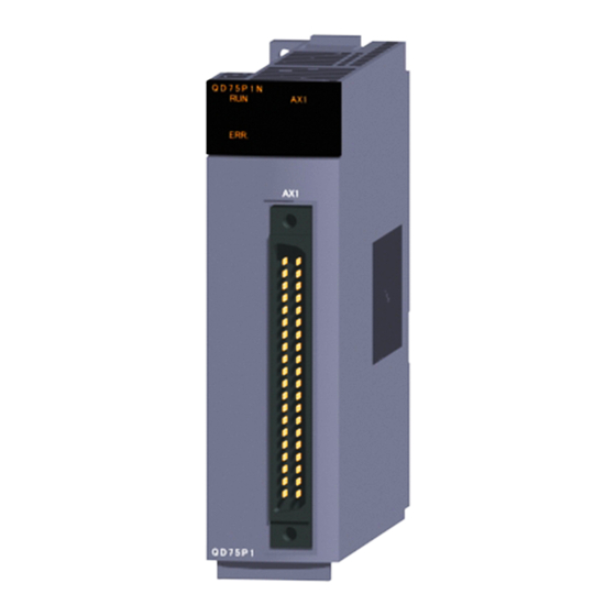
QD75P1N
Mitsubishi Electric QD75P1N Manuals
Manuals and User Guides for Mitsubishi Electric QD75P1N. We have
1
Mitsubishi Electric QD75P1N manual available for free PDF download: User Manual
Mitsubishi Electric QD75P1N User Manual (896 pages)
Type QD75P/QD75D Positioning Module
Brand:
Mitsubishi Electric
| Category:
Control Unit
| Size: 20.5 MB
Table of Contents
Safety Precautions
3
Conditions of Use for the Product
7
Revisions
8
Table of Contents
11
About Manuals
19
Using this Manual
19
Compliance with Emc and Low Voltage Directives
20
Generic Terms and Abbreviations
20
Component List
21
Chapter 3 Part 1 Product Specifications and Handling
23
Product Outline
26
Positioning Control
26
Features of QD75
26
Purpose and Applications of Positioning Control
29
Mechanism of Positioning Control
31
Outline Design of Positioning System
33
Communicating Signals between QD75 and each Module
36
Flow of System Operation
39
Flow of All Processes
39
Outline of Starting
42
Outline of Stopping
44
Outline of Restarting
46
Restrictions on Using a Stepping Motor
47
Function Additions/Modifications According to Function Version B
47
System Configuration
50
General Image of System
50
Configuration List
52
Applicable System
54
How to Check the Function Version and SERIAL no
56
Specifications and Functions
60
Performance Specifications
60
List of Functions
64
QD75 Control Functions
64
QD75 Main Functions
66
Position-Speed Switching Control
66
Current Value Changing
66
NOP Instruction
66
JUMP Instruction
66
Loop
66
Lend
66
Block Start (Normal Start)
67
Condition Start
67
Wait Start
67
Simultaneous Start
67
Repeated Start (for Loop)
67
Repeated Start (for Condition)
67
Multiple Axes Simultaneous Start Control
67
JOG Operation
67
Inching Operation
67
QD75 Sub Functions and Common Functions
68
Software Stroke Limit Function
68
Hardware Stroke Limit Function
68
Speed Change Function
68
Override Function
68
Acceleration/Deceleration Time Change Function
68
Torque Change Function
68
Target Position Change Function
68
Absolute Position Restoration Function
69
Skip Function
70
M Code Output Function
70
Teaching Function
70
Command In-Position Function
70
Acceleration/Deceleration Processing Function
70
Pre-Reading Start Function
70
Deceleration Start Flag Function
70
Stop Command Processing for Deceleration Stop Function
70
Common Functions
71
Parameter Initialization Function
71
Execution Data Backup Function
71
External I/O Signal Logic Switching Function
71
External I/O Signal Monitor Function
71
Combination of QD75 Main Functions and Sub Functions
72
Specifications of Input/Output Signals with CPU Module
74
List of Input/Output Signals with CPU Module
74
Details of Input Signals
75
CPU Module)
75
Specifications of Input/Output Interfaces with External Devices
77
Electrical Specifications of Input/Output Signals
77
Signal Layout for External Device Connection Connector
83
List of Input/Output Signal Details
84
Input/Output Interface Internal Circuit
86
Chapter 4 Installation, Wiring and Maintenance of the Product
89
Outline of Installation, Wiring and Maintenance
90
Installation, Wiring and Maintenance Procedures
90
Names of each Part
91
Handling Precautions
93
Installation
95
Installation Precautions
95
Wiring
96
Wiring Precautions
96
Wiring of the Differential Driver Common Terminal
102
Checking Installation and Wiring
103
Items to Check When Installation and Wiring Are Completed
103
Maintenance
104
Maintenance Precautions
104
Disposal Precautions
104
Chapter 5 Data Used for Positioning Control
105
Types of Data
106
Parameters and Data Required for Control
106
Setting Items for Positioning Parameters
109
Setting Items for OPR Parameters
111
Setting Items for Positioning Data
112
Setting Items for Block Start Data
114
Setting Items for Condition Data
115
Types and Roles of Monitor Data
116
Types and Roles of Control Data
119
List of Parameters
122
Basic Parameters 1
122
Basic Parameters 2
128
Detailed Parameters 1
130
Detailed Parameters 2
140
OPR Basic Parameters
149
OPR Detailed Parameters
156
List of Positioning Data
160
List of Block Start Data
178
List of Condition Data
184
List of Monitor Data
190
System Monitor Data
190
Axis Monitor Data
200
List of Control Data
214
System Control Data
214
Axis Control Data
218
Chapter 6 Sequence Program Used for Positioning Control
239
Precautions for Creating Program
240
List of Devices Used
243
Creating a Program
249
General Configuration of Program
249
Positioning Control Operation Program
250
Positioning Program Examples
253
Program Details
263
Initialization Program
263
Start Details Setting Program
264
Start Program
266
Continuous Operation Interrupt Program
276
Restart Program
278
Stop Program
282
Memory Configuration and Data Process
285
Configuration and Roles of QD75 Memory
286
Buffer Memory Area Configuration
289
Data Transmission Process
290
Chapter 8 Opr Control
299
Outline of OPR Control
300
Two Types of OPR Control
300
Machine OPR
302
Outline of the Machine OPR Operation
302
Machine OPR Method
303
OPR Method (1): Near-Point Dog Method
305
OPR Method (2): Stopper Method 1)
307
OPR Method (3): Stopper Method 2)
310
OPR Method (4): Stopper Method 3)
313
OPR Method (5): Count Method1)
315
OPR Method (6): Count Method 2)
318
Fast OPR
321
Outline of the Fast OPR Operation
321
Chapter 9 Major Positioning Control
323
Outline of Major Positioning Controls
324
Data Required for Major Positioning Control
326
Operation Patterns of Major Positioning Controls
327
Designating the Positioning Address
338
Confirming the Current Value
339
Control Unit "Degree" Handling
341
Interpolation Control
351
Setting the Positioning Data
351
Relation between each Control and Positioning Data
351
1-Axis Linear Control
353
2-Axis Linear Interpolation Control
355
3-Axis Linear Interpolation Control
359
4-Axis Linear Interpolation Control
365
1-Axis Fixed-Feed Control
369
2-Axis Fixed-Feed Control (Interpolation)
371
3-Axis Fixed-Feed Control (Interpolation)
374
4-Axis Fixed-Feed Control (Interpolation)
379
2-Axis Circular Interpolation Control with Sub Point Designation
382
2-Axis Circular Interpolation Control with Center Point Designation
388
3-Axis Helical Interpolation Control with Sub Point Designation
396
3-Axis Helical Interpolation Control with Center Point Designation
404
1-Axis Speed Control
413
2-Axis Speed Control
416
3-Axis Speed Control
419
4-Axis Speed Control
423
Speed-Position Switching Control (INC Mode)
428
Speed-Position Switching Control (ABS Mode)
437
Position-Speed Switching Control
449
Current Value Changing
452
NOP Instruction
457
JUMP Instruction
458
Loop
460
Lend
461
Chapter 10 High-Level Positioning
464
Outline of High-Level Positioning Control
464
Data Required for High-Level Positioning Control
465
Block Start Data" and "Condition Data" Configuration
466
High-Level Positioning Control Execution Procedure
468
Setting the Block Start Data
469
Relation between Various Controls and Block Start Data
469
Block Start (Normal Start)
469
Condition Start
472
Wait Start
473
Simultaneous Start
474
Repeated Start (for Loop)
476
Repeated Start (for Condition)
477
Restrictions When Using the NEXT Start
478
Setting the Condition Data
479
Relation between Various Controls and the Condition Data
479
Multiple Axes Simultaneous Start Control
483
Start Program for High-Level Positioning Control
486
Starting High-Level Positioning Control
486
Other Functions
597
Advertisement
Advertisement
Related Products
Mitsubishi Electric QD75P2N
Mitsubishi Electric QD75P1
Mitsubishi Electric QD75P2
Mitsubishi Electric QD75P4
Mitsubishi Electric QD75P4N
Mitsubishi Electric QD75MH1
Mitsubishi Electric QD75MH2
Mitsubishi Electric QD75MH4
Mitsubishi Electric QD75D1
Mitsubishi Electric QD75D1N
Mitsubishi Electric Categories
Air Conditioner
Controller
Projector
Inverter
Heat Pump
More Mitsubishi Electric Manuals
Login
Sign In
OR
Sign in with Facebook
Sign in with Google
Upload manual
Upload from disk
Upload from URL