Sign In
Upload
Manuals
Brands
Kenwood Manuals
Transceiver
NX-320 Series
Kenwood NX-320 Series Manuals
Manuals and User Guides for Kenwood NX-320 Series. We have
1
Kenwood NX-320 Series manual available for free PDF download: Service Manual
Kenwood NX-320 Series Service Manual (111 pages)
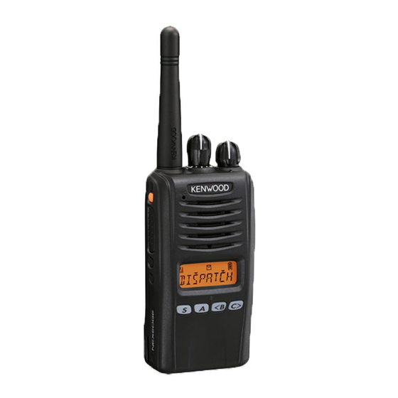
UHF DIGITAL TRANSCEIVER Kenwood NX-320 Series
Brand:
Kenwood
| Category:
Transceiver
| Size: 2.49 MB
Table of Contents
Table of Contents
2
Personal Safety
3
General
3
System Set-Up
4
Modes
5
How to Enter each Mode
5
PC Mode
5
Realignment
5
KPG-22A Description
6
KPG-22U Description
6
KCT-53U Description (USB Adapter: Option)
6
Clone Mode
6
Removing the TX-RX Unit from the Chassis
8
Precautions for Disassembly
8
Removing the Mechanical Stopper
8
Disassembly for Repair
8
Precautions for Reassembly
9
Removing the Speaker Holder
9
Removing the TOP Packing
9
Mounting the Chassis Onto the Case
9
Forming the Flat Cable
10
Changing the Channel Selector from 16-Channel
10
Connection Place of the Antenna Hot Pin and Antenna Terminal
10
Align the SP/MIC Lead Wire
10
Assembly Information (Sheet/Cushion)
11
Receiver System
12
RF Circuit
12
Frequency Confi Guration
12
Circuit Description
12
IF Circuit
13
Audio Amplifier Circuit
13
Squelch Circuit
13
Audio Band Circuit
13
APC Circuit
14
PLL Frequency Synthesizer
14
Drive and Final Amplifier
14
Vox
14
Control Circuit
15
Asic
15
Memory Circuit
15
Local Switch
15
Key Detection Circuit
16
Low Battery Warning
16
Power Supply Circuit
16
Signaling Circuit
16
Display Unit (X54-3760-XX)
18
TX-RX Unit (X57-8050-XX)
18
Components Description
18
Parts List
20
Exploded View
30
Packing
31
Fault Diagnosis of the BGA (Ball Grid Array) IC
32
Checking Power Supply Voltage
32
Trouble Shooting
32
Replacing TX-RX Unit
33
Descriptions of Signal Names
33
TX-RX Unit Information
33
Supplied Accessories of “Service TX-RX Unit”
34
“Service TX-RX Unit” Data
34
After Changing the PCB
34
ESN Label Layout
34
Test Mode Operation Features
35
Controls
35
Panel Test Mode
35
Adjustment (K Type)
35
Panel Tuning Mode
36
Frequency and Signaling
36
Test Frequency
36
Analog Mode Signaling
36
Adjustment Item Supplement
37
Adjustment Item and Adjustment Range
38
Panel Tuning Mode Flow Chart
39
Battery Jig
41
Test Equipment Required for Alignment
41
Nut Wrench
41
Antenna Connector Adapter
41
Radio Check Section
42
Common Section
43
Transmitter Section
45
Necessary Deviation Adjustment Item for each Signaling and Mode
50
Receiver Section
50
Panel Test Mode (E and E2 Models Only)
54
Preparations for Checking/Tuning the Transceiver
54
E Type
54
Panel Tuning Mode (E and E2 Models Only)
55
Adjustment (E Type)
55
Display Unit (X54-3760-XX A/3)
76
Display Unit (X54-3760-XX B/3)
76
Terminal Function
76
SP/MIC Connector Specification
77
Pc Board
78
Display Unit (X54-3760-XX)
78
Tx-Rx Unit (X57-8050-XX)
82
Level Diagram
86
Interconnection Diagram
87
Schematic Diagram
88
Block Diagram
98
Optional Accessories
101
KNB-55L (Li-Ion Battery Pack)
101
KNB-56N (Ni-MH Battery Pack)
101
KNB-57L (Li-Ion Battery Pack)
101
Specifications (K Type)
102
Specifications (E Type)
103
Advertisement
Advertisement
Related Products
Kenwood NEXEDGE NX-320
Kenwood NX-3200
Kenwood NX-3200 K
Kenwood NX-3200 K2
Kenwood NX-3200 K3
Kenwood NX-3200 E
Kenwood NX-3200 E2
Kenwood NX-3200 E3
Kenwood Nexedge NX-320E
Kenwood NX-3220 E
Kenwood Categories
Car Receiver
Transceiver
CD Player
Amplifier
Receiver
More Kenwood Manuals
Login
Sign In
OR
Sign in with Facebook
Sign in with Google
Upload manual
Upload from disk
Upload from URL