Sign In
Upload
Manuals
Brands
Canon Manuals
All in One Printer
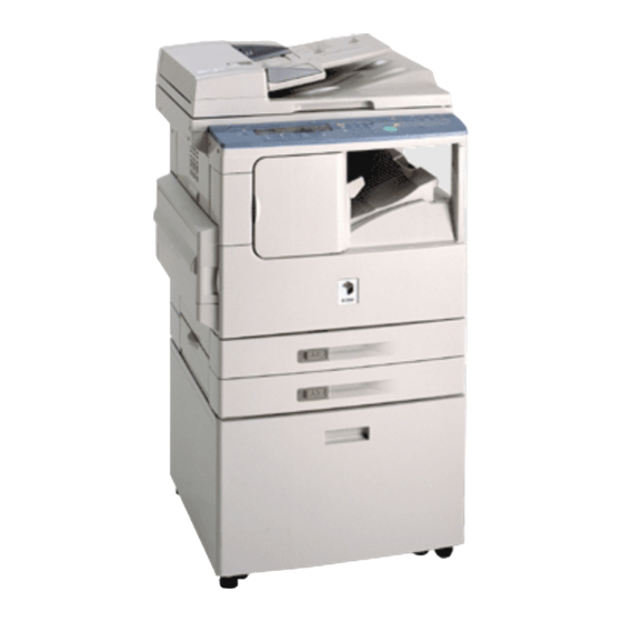
iR1600 Series
Canon iR1600 Series Manuals
Manuals and User Guides for Canon iR1600 Series. We have
4
Canon iR1600 Series manuals available for free PDF download: Service Manual, Reference Manual, Copying Manual
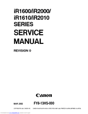
Canon iR1600 Series Service Manual (738 pages)
Brand:
Canon
| Category:
All in One Printer
| Size: 10.35 MB
Table of Contents
Table of Contents
12
System Configuration
8
Chapter 1 Introduction
25
Features
27
Specifications
29
Copier
29
System
29
Type
29
Functions
30
Others
32
Cassette Unit
34
Inner 2-Way Tray
35
Names of Parts
36
Copier
36
External View
36
Cassette Unit
38
Inner 2-Way Tray
39
Copier
40
Cross Section
40
Cassette Unit
42
Inner 2-Way Tray
43
Control Panel
44
Control Panel for a Non-Fax Model
44
Control Panel for a Fax Model
47
Master Password
51
Basic Operation
52
Basic Operation for a Non-Fax Model
52
Chapter 2 Basic Operation
52
Extended Operation
53
User Mode
54
Fax Model
62
Cleaning by the User
85
Cleaning the Fixing Roller
85
Cleaning the Copyboard Glass
87
Guide Assembly
88
Safety and Warnings
90
CDRH Requirements
90
Safety of Laser Light
90
Handling the Laser Unit
91
Safety of the Toner
92
Reproduction Processes
93
Outline
93
Outline of Electrical Circuitry
98
DC Controller PCB
99
Analog Processor PCB
101
Power Supply PCB
101
Inputs to and Outputs from Electrical Components
102
Pickup Solenoid
104
Basic Sequence of Operation (Power-On)
105
Outline
105
Chapter 3 Image Reading/Processing System
111
Outline of Operation
113
Outline
113
Reader Drive System
114
Outline
114
Controlling the Reader Motor
115
Moving the Carriage in Reverse after an Image Scan
115
Detecting the Size of Originals
116
Detection by the Original Size Sensors
116
Outline
116
Originals
117
Detecting the Size of Originals
118
Detection by the ADF
119
Image Processing
120
Outline
120
Contact Sensor
121
Outline of the Contact Sensor
121
Construction of the Contact Sensor (CS)
122
A/D Conversion
123
Shading Correction
123
Black Shading Correction
124
Enlargement/Reduction
126
Enlargement/Reduction in Main Scanning Direction
126
Led Intensity Adjustment
126
Changing the Reproduction Ratio in Sub Scanning Direction
128
Density Adjustment (F-Value Conversion)
129
Density Conversion (LUT, I.e., Look-Up Table Processing)
129
Density Correction (Γ Correction)
129
Edge Emphasis
129
Editing
129
Binary Processing
130
Compression/Expansion, Rotation, and Enlargement/Reduction
130
Error Diffusion
130
Image Memory Control
130
Sdram
130
Output Image Processing
131
Smoothing
131
Disassembly and Assembly
132
Copyboard Glass
133
Removing the Copyboard Glass
133
After Replacing the Copyboard Glass
134
CS Unit
135
Removing the CS Unit
135
Points to Note When Mounting the CS Unit
138
After Replacing the CS Unit
140
Handling the CS Unit
141
Reader Motor
142
The Reader Motor
143
Chapter 4 Laser Exposure System
145
Outline of Operation
147
Outline
147
Basic Sequence of Operation (Laser Exposure System)
149
Generating the Horizontal Signal
150
Outline
150
Signals Used
150
Laser Driver Circuit
152
Laser Control
152
Laser Unit
153
Controlling the Scanner Motor
154
Scanner Pre-Rotation
155
Scanner Unit
157
Chapter 5 Image Formation System
159
Outline of Processes
161
Cleaning Blade
162
Developing Cylinder
162
Drum Unit
162
Paper Path
162
Toner Cartridge
162
Sequence of Operation (Image Formation System)
163
1 Controlling the Primary Charging Roller Bias
164
Outline
164
AC Bias
165
AC Bias Constant Current Control
165
Bias Constant Voltage/Constant Current Control
165
DC Bias
165
DC Bias Constant Voltage Control
165
Turning on and off the Bias
165
Controlling the Developing Bias
166
Outline
166
Controlling the Bias to a Constant Voltage Level
167
Controlling the Developing AC Bias to a Constant Voltage Level
167
Controlling the Developing DC Bias to a Constant Level
167
Controlling the Voltage Level of the Developing DC Bias
167
Turning On/Off the Bias
167
Controlling the Transfer Charging Roller Bias
168
Outline
168
Controlling the Bias to a Constant Current /Voltage Level
169
Controlling the DC Bias to a Constant Current Level
169
Controlling the DC Bias to a Constant Level
169
Turning on and off the Bias
169
Turning on and off the Negative DC Bias
169
Turning on and off the Positive DC Bias
169
Controlling the Output According to Operation Mode
170
Correcting the Voltage Level (ATVC Control)
170
Type of Mode
170
Detecting the Presence/Absence of a Cartridge and the Level of Toner
171
Outline
171
Sequence of Detection (Level of Toner)
172
Monitoring the Waste Toner Case
174
Photosensitive Drum
177
Developing Assembly
178
Transfer Roller
180
Chapter 6 Pickup/Feeding System
181
Outline
183
Specifications and Constructions
183
Arrangement of Major Rollers and Sensors
184
Controlling the Pickup Assembly
185
Controlling the Pickup from the Cassette
185
Outline
185
Pickup Form the Cassette
186
Pickup Retry
188
Detecting the Size of Paper in the Cassette
189
Controlling the Pickup from the Multifeeder Tray
190
Outline
190
Pickup from the Multifeeder Tray
191
Multifeeder Retry Operation
193
Setting the Paper Size for the Multifeeder Tray (User Mode)
193
Controlling the Registration Roller
194
Assembly
194
Detecting the Leading Edge of Paper
194
Roller
194
Detecting Jams
195
Outline
195
Delay Jam
196
Sequence of Jam Detection
196
Stationary Jams
198
Cover Open Jam
199
Jam History
199
Disassembly and Assembly
200
Cassette Pickup Assembly
201
Remove the Cassette Pickup Assembly
201
Removing the Cassette Pickup Roller
203
Removing the Cassette Pickup Solenoid
204
Removing the Feeding/Separation Roller
204
Removing the Paper Size Detecting Switch
204
Removing the Cassette Paper Sensor
205
Removing the Pickup Motor (20 Cpm Model Only)
205
Removing the Retry Sensor
205
Multifeeder Tray Assembly
206
Removing the Multifeeder Tray
206
Removing the Multifeeder Pickup Roller
207
Removing the Multifeeder Paper Sensor
208
Removing the Separation Pad
208
Drive Assembly
209
Removing the Multifeeder Pickup Solenoid
209
Paper Sensor
214
Clutch
215
Chapter 7 Fixing System
217
Outline of Operation
219
Outline
219
Controlling the Fixing Temperature
221
Outline
221
Controlling the Temperature
222
Control at Time of Power-On
223
Control According to the Type of Paper
224
Control at Time of down Sequence
224
Control in ESS (Energy Save Mode)
225
Conditions for Error Detection
226
Control in Response to an Error
226
Detecting an Error
226
Outline
226
Protective Mechanism
228
Disassembly and Assembly
229
Removing the Fixing Assembly
230
Cleaning the Inside of the Fixing Assembly or Replacing Its Parts
233
Removing the Delivery Sensor
233
Removing the Pressure Roller
234
Removing the Fixing Roller/Fixing Heater/Separation Claw
240
Mounting the Fixing Roller/Fixing Heater/Separation Claw
242
Chapter 8 Externals and Auxiliary
249
Control System
249
Power Supply
252
Outline
252
Rated Outputs from the Power Supply PCB
254
High-Voltage Power Supply Circuit
255
Protective Mechanisms
255
Control at Time of Energy Save Mode
256
Control
256
Outline
256
Operation
258
Fan
259
Outline
259
Error Detection
261
Sequence of Operation (Fan Drive)
261
Back-Up Battery
262
Back-Up Mechanism
262
Outline
262
Vanadium Lithium Secondary Battery (BAT2)
262
Lithium Battery (BAT1)
263
Back-Up Data
266
Types of Data
266
Printing out the Back-Up Data List
268
Disassembly and Assembly
269
External Covers
270
Removing the
272
Removing the Control Panel Lower Cover
272
Control Panel
273
Removing the Control Panel
273
Removing the Main
274
Discharge Fan
275
Pcbs
276
Image Processor PCB
277
Removing the RAM DIMM
277
Removing the Analog Processor PCB
278
Removing the ROM DIMM
278
After Replacing the Analog Processor PCB
281
Removing the Power Supply PCB
281
Removing the Cassette Controller PCB (20 Cpm Model Only)
282
Removing the Original Detection/Reader Motor PCB
282
Removing the Printer Board Unit (if Equipped with Printer Functions)
282
Chapter 9 Cassette Unit
288
Pickup Assembly
288
Pickup Control System
288
Cassette Paper Size Detection
291
Cassette Pickup Operation
291
Pickup Control
291
Pickup Re-Try Operation
291
Detecting Jams
292
Delay Jam
292
Jam History
292
Outline
292
Sequence of Jam Detection
292
Stationary Jam
292
Disassembly and Assembly
293
Removing the Cassette Unit
294
Cassette Pickup Assembly
296
Removing the Cassette Pickup Assembly
296
Removing the Cassette Pickup Roller
296
Drive-Related Parts
297
Chapter 10 Inner 2-Way Tray
299
Specifications
301
System
301
Arrangement of Rollers and Sensors
302
Controlling Delivery Operation
303
Controlling Delivery
303
Selecting a Delivery Slot (User Mode)
303
Removing the Inner 2-Way Unit
306
Chapter 11 Installation
313
Selecting the Site of Installation
315
Unpacking and Installing the Machine
317
Points to Note before Starting the Work
317
Installing the Machine
318
Mounting the Drum Unit
318
Removing the Dummy Drum
318
Unpacking and Removing the Fixing Members
318
Mounting the Toner Cartridge
325
Putting Paper in the Cassette
328
Placing Paper in the Multifeeder Tray
332
Checking the Copy Images
334
Selecting the Country/Region through Service Operation
335
Setting the Date/Time (User Mode)
336
Storing the Specifications Report
337
Communications Test
338
Connecting the Line
338
Setting the Dialing Method
338
Setting the Fax Functions (if Equipped with Fax Functions)
338
Checking the Printer Functions (if Equipped with Printer Functions)
339
Relocating the Machine
340
Flow of Accessory Installation
341
Installing the Card Readere-E1 (Accessory)
342
Points to Note for Installation
342
Installation
343
Setting and Checking after Installation
347
Device II (Accessory)
353
Installation to the Copier
354
Chapter 12 Maintenance and Inspection
367
Periodically Replaced Parts
369
Cassette Unit
369
Copier
369
Inner 2-Way Tray
369
Guide to Durables
370
Checking the Timing of Replacement
370
Copier
370
Inner 2-Way Tray
370
Basic Service Work
371
Cleaning During a Visit
372
Points to Note When Storing/Handling the Drum Unit
375
The Drum Unit
376
Troubleshooting
377
Image Adjustment Basic Procedure
379
Standards and Adjustments
381
Image Adjustments
381
Standards for Image Position
381
Adjusting the Image Position
382
Adjusting the Leading Edge Margin for the Printer Unit
383
Printer Functions
383
Adjusting the Image Position for Copying
385
Adjusting the Image Position for ADF Copying
387
Checking the Fixing Roller Pressure (Nip)
389
Fixing System
389
Electrical Parts
390
Gain Auto Adjustment
390
Major Parts
390
When Replacing the Contact Sensor
390
When Replacing the Image Processor PCB
391
Checking the Sensors
394
Chapter 13 Troubleshooting
392
When Replacing the Analog Processor PCB
393
When Replacing the DC Controller PCB
393
Troubleshooting Image/Operation Faults
397
Checking the Originals
397
Copyboard Cover and
397
Making Initial Checks on Image Faults
397
Site of Installation
397
Checking the Drum Unit
398
Checking the Paper
398
Checking the Transfer Charging Roller/Static Eliminator
398
Image Adjustment Basic Procedure
398
Others
398
Blank Page
399
Image Fault Samples
400
The Copy Is too Light
401
The Copy Is too Light. (both Halftone and Solid Black)
401
The Copy Is too Light. (Entire Copy, Appreciably)
401
Troubleshooting Image Faults
401
The Copy Has Uneven Density
404
The Copy Is Foggy
405
The Copy Has Black Lines
406
The Copy Has Black Lines. (Feeding Direction, Fine)
406
The Copy Is Foggy
406
The Copy Has White Lines
407
The Copy Has White Strips
407
The Output Has White Strips
408
The Back of the Copy Is Soiled
409
The Copy Has a Poor Fixing
410
Excessive Margin)
411
The Copy Has Displaced Registration. (Leading Edge, Excessive Margin)
411
The Copy Has Displaced Registration. (Leading Edge, no Margin)
411
Tion. (Leading Edge Extremely Excessive Margin)
411
The Copy Has Blurred Images
412
The Copy Is Foggy
413
The Copy Has Poor Sharpness
414
The Copy Is Blank
415
The Copy Is Solid Black
416
The Copy Has a Black Line (Stream Reading)
417
Troubleshooting Malfunctions
418
AC Power Is Absent
418
DC Power Is Absent
419
Pickup Operation Fails
420
Pickup Operation Fails
421
The Registration Roller Fails to Rotate
423
The Vertical Path Roller Fails to Rotate
423
The Contact Sensor Fails to Go on
424
The Speaker Fails to Operate
424
The 'Add Toner' Message Fails to Go off
425
The 'Add Paper' Message Fails to Go off
426
The 'Add Paper' Message Fails to Go OFF. (Machine and Cassette Unit)
426
The 'Jam' Message Fails to Go off
427
The 'Control Card Set' Message Does Not Go off
428
The 'Controller Card Set' Message Does Not Go on
428
The 'Waste Toner Full' Message Does Not Go off
428
Troubleshooting Feeding Faults
429
Outline
429
Pickup Assembly
430
Transfer/Feeding Assembly
431
Fixing/Delivery Assembly
432
Feeding Fault
433
Feeding Faults
434
Arrangement and Functions of Electrical Parts
435
Outline
435
Checking the Sensors
435
Clutches, Solenoids, Motors, and Fans
436
Sensors
437
Pcbs
438
Switches, Others
440
Cassette Unit
442
Inner 2-Way Tray
444
Variable Resistors (VR), Light-Emitting Diodes (LED), and Check Pins
445
Image Processor PCB
446
DC Controller PCB
447
Power Supply PCB
448
Analog Processor PCB
449
1-Cassette Unit Controller PCB
450
Service Mode
451
Outline
451
Using the Mode
453
Service Mode Menus
454
Registering the Bit Switch (#1 SSSW)
462
Setting the Parameters
462
Menu Switch Setting (#2 MENU)
489
Setting Numeric Parameters (#3 NUMERIC Param.)
491
ISDN Setting (#4C ISDN)
498
NCU Setting (#4B NCU)
498
SPECIAL Setting (#4A SPECIAL)
498
Selecting the Country/Region of Installation (#5 TYPE)
499
Setting Original Read Functions (#6 SCANNER)
499
Setting the Printer Parameters
504
Pdl (#8 Pdl)
507
Counters
508
Generating a Report (#10 REPORT)
511
Downloading (#11 DOWNLOAD)
512
Clear (#12 CLEAR)
513
Resetting the CS Unit Position (#14 CS SET)
514
ROM Indication (#13 ROM)
514
Test Mode (TEST MODE)
515
Outline
515
Test Mode Menu
516
D-RAM Test
521
1:D-Ram
522
CCD Test
523
PRINT Test (3: PRINT)
524
MODEM NCU Test
525
Faculty Test
528
Book Read Test
538
Report
539
Service Report
542
Service Error Code
552
Self Diagnosis
554
Error Codes
555
E010/E100
557
E500/E514
561
Finisher Error Codes
561
Fax Error Code
568
User Error Codes
572
Service Error Codes
579
Chapter 14 Version up
607
Outline
607
Upgrading
607
Upgrading by Downloading
609
Installing the Firmware
616
Software
619
Downloading
620
Downloading for G3 FAX
626
Finisher-L1
627
Outline
633
Backing up Data
633
Making Preparations
633
Making Connections
634
General Timing Chart
649
General Circuit Diagram
651
Fax Board
661
Communication System
677
Line Selection Number
677
List of Functions
678
Faults at Time of Installation
682
General Faults
682
Correcting Communication Faults
683
Initial Identification of a Fault
683
Correcting Faults
684
Advertisement
Canon iR1600 Series Service Manual (554 pages)
Brand:
Canon
| Category:
All in One Printer
| Size: 10.69 MB
Table of Contents
Table of Contents
10
System Configuration
7
Chapter 1 Introduction
21
Features
23
Specifications
25
Copier
25
System
25
Type
25
Functions
26
Others
28
Cassette Unit
30
Inner 2-Way Tray
31
Names of Parts
32
Copier
32
External View
32
Cassette Unit
34
Inner 2-Way Tray
35
Copier
36
Cross Section
36
Cassette Unit
38
Inner 2-Way Tray
39
Control Panel
40
Basic Operation
43
Extended Operation
43
User Mode
44
Cleaning by the User
52
Reading Glass, and Copyboard Cover White Plate
54
Safety and Warnings
55
CDRH Requirements
55
Safety of Laser Light
55
Handling the Laser Unit
56
Safety of the Toner
57
Reproduction Processes
58
Outline
58
Basic Operation
63
Outline of Electrical Circuitry
64
DC Controller PCB
65
Power Supply PCB
67
Inputs to and Outputs from Electrical Components
68
Wiring Diagram of Electrical Components (2/2)
70
Basic Sequence of Operation (Power-On)
71
Outline
71
Basic Sequence of Operation (Printing)
73
Controlling the Main Motor (M101)
75
Outline
75
Chapter 3 Image Reading/Processing System
77
Outline of Operation
79
Outline
79
Reader Drive System
80
Outline
80
Controlling the Reader Motor
81
Moving the Carriage in Reverse after an Image Scan
81
Detecting the Size of Originals
82
Detection by the Original Size Sensors
82
Outline
82
Detecting the Size of Originals
84
Detection by the ADF
85
Image Processing
86
Outline
86
Contact Sensor
87
Outline of the Contact Sensor
87
Construction of the Contact Sensor (CS)
88
A/D Conversion
89
Shading Correction
89
Black Shading Correction
90
Re-Ordering
90
White Shading Correction
90
Abc
91
Enlargement/Reduction
92
Enlargement/Reduction in Main Scanning Direction
92
LED Intensity Adjustment
92
Changing the Reproduction Ratio in Sub Scanning Direction
94
Density Adjustment (F-Value Conversion)
95
Density Conversion (LUT, I.e., Look-Up Table Processing)
95
Density Correction
95
Edge Emphasis
95
Editing
95
Binary Processing
96
Compression/Expansion, Rotation, and Enlargement/Reduction
96
Error Diffusion
96
Image Memory Control
96
Sdram
96
Output Image Processing
97
Smoothing
97
Disassembly and Assembly
98
Copyboard Glass
99
Removing the Copyboard Glass
99
After Replacing the Copyboard Glass
100
Copyboard Glass
101
CS Unit
101
Removing the CS Unit
101
Points to Note When Mounting the CS Unit
104
After Replacing the CS Unit
106
Points to Note When Handling the CS Unit
107
Reader Motor
108
Removing the Reader Motor
108
Points to Note When Mounting the Reader Motor
109
Chapter 4 Laser Exposure System
111
Outline of Operation
113
Outline
113
Basic Sequence of Operation (Laser Exposure System)
115
Generating the Horizontal Signal
116
Outline
116
Signals Used
116
Laser Driver Circuit
118
Laser Control
118
Laser Unit
119
Controlling the Scanner Motor
120
Scanner Pre-Rotation
121
Scanner Unit
123
Chapter 5 Image Formation System
125
Outline of Processes
127
Sequence of Operation (Image Formation System)
129
1 Controlling the Primary Charging Roller Bias
130
Outline
130
AC Bias
131
AC Bias Constant Current Control
131
Bias Constant Voltage/Constant Current Control
131
DC Bias
131
DC Bias Constant Voltage Control
131
Turning on and off the Bias
131
Controlling the Developing Bias
132
Outline
132
AC Bias
133
Controlling the Bias to a Constant Voltage Level
133
Controlling the Developing AC Bias to a Constant Voltage Level
133
Controlling the Developing DC Bias to a Constant Level
133
Controlling the Voltage Level of the Developing DC Bias
133
DC Bias
133
Turning On/Off the Bias
133
Controlling the Transfer Charging Roller Bias
134
Outline
134
Controlling the Bias to a Constant Current /Voltage Level
135
Controlling the DC Bias to a Constant Current Level
135
Controlling the DC Bias to a Constant Level
135
Turning on and off the Bias
135
Turning on and off the Negative DC Bias
135
Turning on and off the Positive DC Bias
135
Controlling the Output According to Operation Mode
136
Correcting the Voltage Level (ATVC Control)
136
Type of Mode
136
Detecting the Presence/Absence of a Cartridge and the Level of Toner
137
Outline
137
Sequence of Detection (Level of Toner)
138
Monitoring the Waste Toner Case
140
Outline
140
Sequence of Operation
141
Disassembly and Assembly
142
Cleaning the Photosensitive Drum
143
Photosensitive Drum
143
Removing the Drum Unit
143
Developing Assembly
144
Transfer Roller
146
Chapter 6 Pickup/Feeding System
147
Outline
149
Specifications and Constructions
149
Arrangement of Major Rollers and Sensors
150
Controlling the Pickup Assembly
151
Controlling the Pickup from the Cassette
151
Outline
151
Pickup Form the Cassette
152
Pickup Retry
154
Detecting the Size of Paper in the Cassette
155
Controlling the Pickup from the Multifeeder Tray
156
Outline
156
Pickup from the Multifeeder Tray
157
Multifeeder Retry Operation
159
Setting the Paper Size for the Multifeeder Tray (User Mode)
159
Controlling the Registration Roller
160
Detecting the Leading Edge of Paper
160
Detecting Jams
161
Outline
161
Delay Jam
162
Sequence of Jam Detection
162
Stationary Jams
164
Cover Open Jam
165
Cassette Pickup Assembly
167
Remove the Cassette Pickup Assembly
167
Assembly
168
Removing the Cassette Pickup Roller
169
Remove the Cassette Pickup
170
Removing the Cassette Pickup Solenoid
170
Removing the Feeding/Separation Roller
170
Removing the Paper Size Detecting Switch
170
Removing the Cassette Paper Sensor
171
Removing the Pickup Motor (Ir2000 Only)
171
Removing the Retry Sensor
171
Multifeeder Tray Assembly
172
Removing the Multifeeder Tray
172
Removing the Manual Feed Pickup Roller
173
Removing the Multifeeder Paper Sensor
174
Removing the Separation Pad
174
Removing the Multifeeder Pickup Solenoid
175
Drive Assembly
175
Removing the Drive Assembly
175
Registration Roller Assembly
179
Removing the Registration Roller
179
Paper Sensor
180
Removing the Registration Clutch
181
Chapter 7 Fixing System
183
Outline of Operation
185
Outline
185
Controlling the Fixing Temperature
187
Outline
187
Controlling the Temperature
188
Control at Time of Power-On
189
Control According to the Type of Paper
190
Control at Time of down Sequence
190
Control in ESS (Energy Save Mode)
191
Control in Response to an Error
192
Detecting an Error
192
Detection
192
Outline
192
Protective Mechanism
194
Removing the Delivery Sensor
199
Removing the Pressure Roller
200
Fixing Heater/Separation Claw
206
Fixing Heater/Separation Claw
208
Chapter 8 Externals and Auxiliary
211
Control System
211
Control Panel
213
The Machine's Control Panel Has the Following Construction
213
Outline
214
Power Supply
214
Rated Outputs from the Power Supply PCB
216
Protective Mechanisms
217
Mounting the Fixing Roller/Fixing Heater/Separation Claw
218
Control at Time of Energy Save Mode
218
Outline
218
Control
218
Operation
220
Fan
221
Outline
221
Control
222
Controlling the Speed
222
Error Detection
223
Sequence of Operation (Fan Drive)
223
Back-Up Battery
224
Back-Up Mechanism
224
Outline
224
Lithium Battery (BAT1)
225
Back-Up Data
227
Types of Data
227
Printing out the Back-Up Data List
228
Disassembly and Assembly
229
External Covers
230
Removing the Front Cover
232
Control Panel
233
Main Motor
234
Removing the Heat Discharge Fan
235
After Replacing the DC Controller Pcb
236
Removing the DC Controller Pcb
236
Removing the Power Supply Pcb
241
Chapter 9 Cassette Unit
243
Outline
245
Specifications and Construction
245
Arrangement of Major Rollers and Sensors
246
Pickup Assembly
248
Cassette Paper Size Detection
251
Cassette Pickup Operation
251
Pickup Control
251
Pickup Re-Try Operation
251
Detecting Jams
252
Delay Jam
252
Jam History
252
Outline
252
Sequence of Jam Detection
252
Stationary Jam
252
Disassembly and Assembly
253
Removing the Cassette Unit
254
Cassette Pickup
256
Removing the Re-Try Sensor
256
Pcbs
257
Controller PCB
257
Removing the Cassette Unit
257
Drive-Related Parts
257
Removing the Pickup Motor
257
Chapter 10 Inner 2-Way Tray
259
Specifications
261
System
261
Arrangement of Rollers and Sensors
262
Controlling Delivery Operation
263
Selecting a Delivery Slot (User Mode)
263
Removing the Inner 2-Way Unit
266
Chapter 11 Installation
273
Selecting the Site of Installation
275
Unpacking and Installing the Machine
277
Points to Note before Starting the Work
277
Installing the Machine
278
Unpacking and Removing the Fixing Members
279
Removing the Dummy Drum
281
Mounting the Drum Unit
283
Mounting the Toner Cartridge
285
Putting Paper in the Cassette
288
Placing Paper in the Multifeeder Tray
292
Checking the Copy Images
294
Service Mode
295
Service Operation
295
Setting the Date/Time
296
Service Report
297
Checking the Printer Functions
298
Functions)
298
Relocating the Machine
299
Installing the Card Readere-E1 (Accessory)
300
Points to Note for Installation
300
Installation
301
Installing the Image RAM (Accessory)
305
Installation
305
Chapter 12 Maintenance and Inspection
307
Periodically Replaced Parts
309
Cassette Unit
309
Copier
309
Inner 2-Way Tray
309
Guide to Durables
310
Cassette Unit
310
Checking the Timing of Replacement
310
Copier
310
Inner 2-Way Tray
310
Basic Service Work
311
Cleaning During a Visit
312
Points to Note When Storing/Handling the Drum Unit
315
The Drum Unit
316
Image Adjustment Basic Procedure
319
Image Adjustment Basic
319
Chapter 13 Troubleshooting
320
Standards and Adjustments
321
Image Adjustments
321
Standards for Image Position
321
Adjusting the Image Position
322
Adjusting the Leading Edge Margin for the Printer Unit (if Equipped Printer Functions)
323
Adjusting the Image Position for Copying
325
Fixing System
327
Electrical Parts
328
Gain Auto Adjustment
328
Major Parts
328
When Replacing the Contact Sensor
328
When Replacing the Image Processor PCB
329
Troubleshooting
329
When Replacing the Analog Processor PCB
330
When Replacing the DC Controller PCB
330
Checking the Sensors
331
Troubleshooting Image/Operation Faults
334
Checking the Originals
334
Copyboard Cover and Copyboard Glass (Standard White Plate)
334
Making Initial Checks on Image Faults
334
Site of Installation
334
Checking the Drum Unit
335
Checking the Paper
335
Checking the Transfer Charging Roller/Static Eliminator
335
Image Adjustment Basic Procedure
335
Others
335
Image Fault Samples
338
Troubleshooting Image Faults
339
The Copy Is too Light
339
The Copy Has Uneven Density
342
The Copy Is Foggy
343
The Copy Has Black Lines
344
The Copy Is Foggy
344
The Copy Has White Lines
345
The Copy Has White Strips
345
The Output Has White Strips
346
The Back of the Copy Is Soiled
347
The Copy Has a Poor Fixing
348
The Copy Has Displaced Registration. (Leading Edge Extremely Excessive Margin)
349
The Copy Has Displaced Registration. (Leading Edge, Excessive Margin)
349
The Copy Has Displaced Registration. (Leading Edge, no Margin)
349
The Copy Has Blurred Images
350
The Copy Is Foggy. (Cross-Feeding Direction)
351
The Copy Has Poor Sharpness
352
The Copy Is Blank
353
The Copy Is Solid Black
354
Troubleshooting
354
AC Power Is Absent
355
Malfunctions
355
DC Power Is Absent
356
Pickup Operation Fails
357
Pickup Operation Fails
358
Pickup Operation Fails
359
The Registration Roller Fails to Rotate
360
The Vertical Path Roller Fails to Rotate
360
The Contact Sensor Fails to Go on
361
The Speaker Fails to Operate
361
The 'Add Toner' Message Fails to Go off
362
The 'Add Paper' Message Fails to Go off
363
The 'Add Paper' Message Fails to Go OFF. (Machine and Cassette Unit)
363
The 'Jam' Message Fails to Go off
364
The 'Control Card Set' Message Does Not Go off
365
The 'Controller Card Set' Message Does Not Go on
365
The 'Waste Toner Full' Message Does Not Go off
365
Troubleshooting Feeding Faults
366
Outline
366
Pickup Assembly
367
Transfer/Feeding Assembly
368
Fixing/Delivery Assembly
369
Feeding Fault (Double Feeding)
370
Feeding Faults (Wrinkling)
371
Arrangement and Functions of Electrical Parts
372
Checking the Sensors
372
Outline
372
Clutches, Solenoids, Motors, and Fans
373
Sensors
374
Pcbs
375
Switches, Others
377
Cassette Unit
379
Inner 2-Way Tray
381
Variable Resistors (VR), Light-Emitting Diodes (LED), and Check Pins
382
Image Processor PCB
383
DC Controller PCB
384
Power Supply PCB
385
Analog Processor PCB
386
1-Cassette Unit Controller PCB
387
Service Mode
388
Outline
388
Using the Mode
390
Service Mode Menus
391
Registering the Bit Switch (#1 SSSW)
395
Setting the Parameters
395
Setting Numeric Parameters (#3 NUMERIC Param.)
397
Selecting the Country/Region of Installation (#5 TYPE)
400
Setting Original Read Functions (#6 SCANNER)
401
Pdl (#8 Pdl)
404
Setting the Printer Parameters (#7 PRINTER)
404
Counters (#9 COUNTER)
405
Generating a Report (#10 REPORT)
408
Downloading (#11 DOWNLOAD)
409
Clear (#12 CLEAR)
410
Resetting the CS Unit Position (#14 CS SET)
411
ROM Indication (#13 ROM)
411
Outline
412
Test Mode (TEST MODE)
412
Test Mode Menu
413
D-RAM Test (1: D-RAM)
416
CCD Test (2: CCD TEST)
418
PRINT Test (3: PRINT)
419
Faculty Test (6: FACULTY TEST)
420
Book Read Test (8: BOOK TEST)
426
Report
427
User Report
427
Service Report
428
System Data List
429
Self Diagnosis
435
Outline
435
Error Codes
436
Error Codes Used for the Machine
436
Finisher Error Codes
441
Chapter 14 Version up
449
Upgrading
451
Outline
451
Upgrading by Downloading
453
Before Starting the Work
453
Installing the USB Driver (Only if Windows 98 or Windows 98SE)
454
Installing the Firmware
457
Software
460
Finisher-L1
467
Appendix
473
General Timing Chart
475
General Circuit Diagram
477
E Inner 2-Way Tray
481
F Special Tools
483
G Solvents and Oils
485
Canon iR1600 Series Reference Manual (194 pages)
Canon Printer User Manual
Brand:
Canon
| Category:
All in One Printer
| Size: 3.36 MB
Table of Contents
Table of Contents
4
How to Use this Manual
8
Symbols Used in this Manual
8
Buttons Used in this Manual
8
Illustrations Used in this Manual
8
Laser Safety
9
Additional Information
9
International Energy Star-Program
10
About Trademarks
10
Important Safety Instructions
11
Installation
11
Power Supply
12
Handling
12
Maintenance and Inspections
14
Consumables
15
Others
15
Legal Limitation on Usage of Your Product and the Use of Images
16
Operation of the Machine and Terms Used in this Manual
17
Chapter 1 Before You Start Using this Machine
20
About the Installation Location and Handling
20
Installation Precautions
20
Avoid Installing the Machine in the Following Locations
20
Select a Safe Power Supply
23
Provide Adequate Installation Space
23
Moving the Machine
24
Handling Precautions
25
What the Ir2000/1600 Series Machine Can Do
27
Reserving Next Job While Current Job Is in Operation
27
Setting Specifications to Suit Your Needs
27
Functions that Conserve Power Consumption
28
Department ID Management
28
Checking the Job Status
28
Parts and Their Functions
29
External View
29
Internal View
31
Control Panel Parts and Functions
32
Main Power and Control Panel Power
34
How to Turn on the Main Power
34
Please Wait
35
Energy Saver Button ( )
37
Turning off the Main Power When Optional Hard Disk Is Attached
37
The System Settings of this Machine
38
Entering the Department ID and Password
39
After Turning the Power on
39
After Finishing Operations of the Machine
40
Placing Originals
41
Orientation of Originals
42
Placing an Original on the Platen Glass
43
Placing Originals in the Optional Feeder (ADF-J1)
46
Making Prints Using the Stack Bypass
48
Select Paper
52
Plain Paper
52
Multi-Function Operation
53
Available Paper Stock
54
Chapter 2 Checking Job
58
Flow of Checking/Canceling Operations
58
Canceling a Job
59
Canceling with (Stop)
59
Canceling from the Monitor Screen
60
Cancel Copying
61
Chapter 3 Selecting and Storing Settings to Suit Your Needs
64
Additional Functions Settings Table
64
Setting Specifications that Are Common to each Function (Common Settings)
67
Setting Keypad Volume, Alarm Volume, Printing End Tone, and Scanning End Tone
67
Common Settings
68
Volume Control
68
Setting the Power Consumption in Energy Saver Mode
69
Setting a Paper Drawer for Auto Paper Selection/Auto Drawer Switching
70
Setting the Standard Paper for the Stack Bypass
71
Setting the Paper Type for the Drawer
73
Setting the Rotate Printing
73
Setting a Dedicated Tray for each Function
74
Tray Settings
75
Selecting the Display Language
76
Setting the Timer (Timer Settings)
77
Setting the Current Date and Time
77
Setting the Auto Clear
78
Timer Settings
79
Auto Clear Time
79
Setting the Energy Saver Mode
80
Setting the Daily Timer
81
Setting the Date Format
82
Printing Reports (Print Lists)
84
Printing the User's Data List
84
Printing the Department ID Management List
85
Canceling Printing of Reports
85
Chapter 4 System Management Settings
88
Setting System Administrator Information (System Settings)
88
Setting the System Administrator ID
88
System Settings
89
Setting the System Password
90
Setting the Department ID Management
91
Setting the Use of Department ID Management
91
Setting the Department ID Management Information
93
Copy Limits
94
Checking the Counter Information
95
Restricting the Operation by Department ID
96
Specifying Whether or Not to Accept Print Jobs of Unknown ID
97
Chapter 5 Routine Maintenance
100
Loading Paper
100
Loading Paper in the Paper Drawers
100
Adjusting a Paper Drawer to Hold a Different Paper Size
103
Replacing the Toner Cartridge
108
Replacing the Drum Cartridge
114
Routine Cleaning
120
Cleaning the Platen Glass/Rear Side of Platen Glass Cover
120
Cleaning the Feeder
121
Cleaning the Roller
124
Roller Cleaning
126
Consumables
127
Advertisement
Canon iR1600 Series Copying Manual (70 pages)
Canon Copier User Manual
Brand:
Canon
| Category:
All in One Printer
| Size: 1.59 MB
Table of Contents
Chapter 1 Basic Copying
2
Chapter 1 Basic Copying
3
Chapter 2 Useful Copy Functions
3
Chapter 4 Appendix
3
Table of Contents
4
How to Use this Manual
6
Symbols Used in this Manual
6
Buttons Used in this Manual
6
Illustrations Used in this Manual
6
What the Ir2000/1600 Series Machine Can Do
8
Flow of Copy Operations
9
Chapter 2 Useful Copy Functions
11
Cancel Copying
12
Entering the Copy Quantity
13
Specifying the Required Number of Copies
13
Changing the Copy Quantity
13
Selecting the Copy Paper Size (Paper Select)
14
Automatic Paper Selection (Auto Paper Selection)
14
Specifying Paper Size and Type (Manual Paper Selection)
15
Adjusting Exposure and Image Quality
17
Adjusting Copy Exposure
17
Selecting Image Quality
18
Automatic Adjustment of Exposure and Image Quality
20
Changing the Copy Ratio (Copy Ratio)
21
Enlarging/Reducing Originals to a Standard Size (Preset Zoom)
21
Specifying the Copy Ratio by % (Zoom Designation)
22
Collating Copies (Finisher)
24
Collating Copies into Sets in Page Order (Collate)
26
Collating Pages and Stapling (Staple)
28
Reserved Copying
29
Reserving a Copy Job While Printing
29
Interrupting the Current Job to Make Priority Copies (Interrupt Mode)
31
Useful Copy Functions
33
Copying Facing Pages in a Book on Two Separate Sheets of Paper (Two
34
Special Features
35
Making Copies with Margins (Margin)
37
Left Margin
38
Erasing Shadows and Frame Lines from Copies (Frame Erase)
39
Making Copies Erasing the Frame of the Originals (Original Frame Erase)
41
Making Copies Erasing the Book Frame (Book Frame Erase)
43
Making Copies Erasing Binding Holes Etc. (Binding Erase)
44
Hole Punch Erase
45
Original Size
45
Frame Erase Width
45
Reducing Two Originals to Fit on a Single Copy Sheet (2 on 1 Combination)
47
Original Size
48
Chapter 3 Setting/Storing Specifications of the Copy Function
51
Copy Settings List
52
Changing the Current Standard Settings
53
Setting the Standard Exposure
53
Copy Settings
54
Setting the Standard Zoom Ratio
55
Setting the Standard Copy Quantity
56
Setting the Standard Frame Erase Width
57
Setting the Automatic Collate On/Off
58
Setting the Rotate Collate On/Off
59
Setting the Sharpness
60
Setting the Prescan Function
62
Advertisement
Related Products
Canon iR1610 Series
Canon iR1022F
Canon iR1022iF
Canon iR1570F
Canon iR1200 Series
Canon iR1024 Series
Canon iR1025 Series
Canon SmartBase iR1200s
Canon iR1019 Series
Canon imagerunner ir1133
Canon Categories
Printer
Digital Camera
All in One Printer
Camcorder
Scanner
More Canon Manuals
Login
Sign In
OR
Sign in with Facebook
Sign in with Google
Upload manual
Upload from disk
Upload from URL