Sign In
Upload
Manuals
Brands
Canon Manuals
All in One Printer
CiRC2880
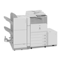
Canon CiRC2880 Manuals
Manuals and User Guides for Canon CiRC2880. We have
1
Canon CiRC2880 manual available for free PDF download: Service Manual
Canon CiRC2880 Service Manual (774 pages)
Brand:
Canon
| Category:
All in One Printer
| Size: 26.88 MB
Table of Contents
Table of Contents
6
Chapter 8 Pickup/Feeding System
14
Chapter 18 Upgrading
26
Chapter 1 Introduction
27
System Construction
30
System Configuration 1 (Delivery Accessories)
30
System Configuration Overview (Delivery Accessories)
30
System Configuration 2 (Delivery Accessories)
31
System Configuration 3 (Delivery Accessories)
33
System Configuration (Delivery Accessories)
34
System Configuration (Pickup/Original Processing Accessories)
36
Cassette Heater System Configuration 1
39
System Configuration (Printing/Transmission Accessories) (USA)
39
System Configuration (Printing/Transmission Accessories)
40
Functions of Printing/Transmission Accessories
42
Functions of Printing/Transmission Accessories (USA)
42
Other Options
43
Product Specifications
43
External View
43
Names of Parts
43
Cross Section
45
Points to Note about Turning off the Main Power Switch
46
Turning on the Power Switch
46
Using the Machine
46
Common Settings
48
User Mode Items
48
Common Settings
51
Adjustment/Cleaning
53
Timer Settings
53
Report Settings
54
System Settings
54
System Settings
58
Communications Settings
60
Copy Settings
60
Address Book Settings
63
Mail Box Settings
63
Cleaning
65
User Maintenance
65
Inspection
69
CDRH Act
71
Handling of Laser System
71
Laser Safety
71
Safety
71
Notes When Handling a Lithium Battery
72
Safety of Toner
72
Notes before It Works Serving
73
Product Specifications
73
Type and Function
73
Others
74
Function List
75
Others
75
Print Speed (Image)
75
Type of Paper
75
Type of Paper
77
Chapter 2 Installation
79
Making Pre-Checks
83
Selecting the Site of Installation
83
Check to Make before Installation
84
Combination Table of Accessory Installation
84
Checking the Contents
86
Unpacking and Installation
88
Installation of the Drum Unit
88
Installation of the Scanner
88
Unpacking
88
Installation of the Toner Retainer
93
Attaching Other Parts
94
Connection of the Cable
94
Points to Note When Turning off the Main Power
94
Automatic Gradation Correction
96
Fixing the Machine in Place
96
Setting up the Cassette
96
Adjusting the Image Position
97
Checking the Connection to the Network
100
Making Checks Using a Remote Host Address
100
Using PING
100
Troubleshooting the Network
100
Making a Check Using a Local Host Address
100
Making Checks Using a Loopback Address
100
Checking the Images/Operations
101
Checking the Images
101
Relocating the Machine
101
Installing the Copy Tray
101
Checking the Components
101
Installation Procedure
101
Turning off the Machine
101
Installing the Card Reader
102
Installation Procedure in the Imageware Accounting Manager (Hereinafter Referred to Iwam Environment
104
Installing the Original Tray
105
Installing the Key Switch Unit
106
Checking after Installation
107
Turning off the Host Machine
108
Installing the Voice Operation Kit
112
Turning off the Host Machine
113
Installing the Wireless Network Interface Adapter
120
Turning off the Host Machine
121
Affixing the Label
124
Cleaning the Copyboard Glass
126
Affixing Labels
129
Turning off the Host Machine
130
Turning off the Host Machine
131
Construction/Basic Sequence
136
Construction
138
Functional Construction
138
Chapter 3 Basic Operation
139
Connections Among Major Pcbs
139
Basic Sequence
140
Basic Sequence of Operations at Power-On
140
Basic Sequence of Operations for a Print Job (Full Color)
140
Basic Sequence of Operations for a Print Job (Mono Color)
141
Table of Contents
145
Construction
147
Construction and Functions
147
Construction of the Electrical Circuitry
148
Sram Pcb
148
Start-Up Sequence
150
Overview
150
Actions When HDD Error
153
E602 in Detail
153
Image Processing
157
Overview of the Flow of Image Data
157
Reader Input Image Processing
157
Printer Output Image Processing
159
Compression, Decompression, and Edit Processing Blocks
160
Flow of Image Data
160
Flow of Image Data for Copier Functions
160
Flow of Image Data for Box Functions
161
Flow of Image Data for SEND Functions
161
Flow of Image Data for Fax Reception Functions
162
Flow of Image Data for Fax Transmission Functions
162
Flow of Image Data for PDL Functions
163
Parts Replacement Procedure
164
Before Removing the Main Controller Box
164
Before Removing the Main Controller PCB
164
Controller Box
164
Main Controller PCB (Main)
164
Removing the Controller Box
164
Removing the Main Controller PCB
164
Before Removing the Main Controller PCB (Sub SJ-A)
165
Before Removing the Main Controller PCB (Sub-PDRAM-A)
165
Before Removing the Main Controller PCB (Sub-R-A)
165
Main Controller PCB (Sub PDRM-A)
165
Main Controller PCB (Sub R-A)
165
Main Controller PCB (Sub SJ-A)
165
Removing the Main Controller PCB (Sub SJ-A)
165
Removing the Main Controller PCB (Sub-PDRAM-A)
165
Removing the Main Controller PCB (Sub-R-A)
165
Replacing Main Controller PCB
165
Chapter 4 Main Controller
166
Main Controller PCB (Sub SJ-A)
166
Before Removing the Main Controller PCB (Sub RB-A2)
167
Before Removing the SRAM
167
Removing the Main Controller PCB (Sub RB-A2)
167
Sram Pcb
167
Before Removing the Boot ROM PCB
168
Before Removing the Image Memory (SDRAM) PCB
168
Boot ROM PCB
168
Image Memory (SDRAM)
168
Removing the Boot ROM PCB
168
Removing the Image Memory (SDRAM) PCB
168
Removing the SRAM
168
When Replacing the SRAM PCB
168
Before Removing the HDD
169
Hdd
169
Removing the HDD
169
When Replacing the HDD
169
Before Removing the Controller Fan
170
Controller Fan
170
Removing the Controller Fan
170
Table of Contents
173
Construction
175
Specifications, Control Mechanisms, and Functions
175
Major Components
175
Construction of the Control System
176
Reader Controller PCB
178
Basic Sequence
179
Basic Sequence of Operations at Power-On
179
Basic Sequence of Operations in Response to a Press on the Start Key (Book Mode, 1 Original)
179
Basic Sequence of Operations in Response to a Press on the Start Key (ADF Mode, 1 Original)
180
Various Control Mechanisms
181
Controlling the Scanner Drive System
181
Overview
181
Reader Motor Control
181
Contact Image Sensor (CIS)
183
Overview
183
Analog Control Inside the Contact Image Sensor (CIS)
184
Enlargement/Reduction
184
Changing the Magnification in Main Scanning Direction
184
Changing the Magnification in Sub Scanning Direction
184
Controlling the Scanning Lamp
185
Activation Control
185
Error Detection
185
Overview
185
Scanning Lamp
185
Detecting the Size of Originals
185
Overview of Detection Operation
187
Points of Original Size Detection
187
Dirt Sensor Control
189
Overview
189
Image Processing
191
Overview
191
A/D Conversion of the CCD Output
192
Driving the CCD
192
Gain Correction and Offset Correction for the CCD Output
192
Shading Adjustment
193
Shading Correction
193
Shading Correction (Outline)
193
Parts Replacement Procedure
194
Copyboard Glass
194
After Replacing the Copyboard Glass
194
Removing the Copyboard Glass
194
After Replacing the ADF Reading Glass
195
Removing the ADF Reading Glass
195
Reader Controller PCB
196
Before Removing the Reader Controller PCB
196
Before Replacing the Reader Controller PCB
196
Removing the Reader Controller PCB
196
After Replacing the Reader Controller PCB
197
Inverter PCB
198
Before Removing the Inverter PCB
198
Removing the Inverter PCB
198
Contact Sensor
199
Before Removing the Contact Image Sensor (CIS)
199
Removing the Contact Image Sensor (CIS)
199
After Replacing the CIS
200
Scanner Motor
199
Before Removing the Scanner Motor
199
Removing the Scanner Motor
199
Original Cover Sensor
200
Before Removing the Copyboard Cover Open/Closed Sensor (Front/Rear)
200
Removing the Copyboard Cover Open/Closed Sensor (Front/Rear)
200
Original Sensor
201
Contact Sensor HP Sensor
201
Construction/Various Control
205
Construction
207
Overview
207
Specifications, Control Mechanisms, and Functions
207
Various Control
209
Controlling the Laser Activation Timing
209
Turning on and off the Laser Light
209
Controlling Synchronization in Main Scanning Direction
210
Controlling Synchronization in Sub Scanning Direction
211
BD Correction
213
APC Control
215
Chapter 6 Laser Exposure
215
Controlling the Intensity of Laser Light
215
Controlling the Laser Scanner Motor
216
Parts Replacement Procedure
218
After Replacing the Laser Scanner Unit
219
Table of Contents
222
Construction
224
Specifications, Control Mechanisms, and Functions
224
Overview
225
Printing Process
226
Static Image Formation Block
227
Developing Block
229
Transfer Block
230
Fixing Block
231
ITB Cleaning Block
232
Photosensitive Drum Cleaning Block
232
Driving and Controlling the High-Voltage System
233
Overview
233
Generation of the Primary Charging Bias
234
Generation of the Developing Bias
234
Generation of the Primary Transfer Bias
235
Generation of the Secondary Transfer Bias
235
Image Stabilization Control
235
Overview of Image Stabilization
235
Timing of Image Stabilization Control
236
Drum Film Thickness Detection
237
ATR Control
238
D-Max Control
239
PASCAL Control
242
D-Half Control
243
ARCDAT Control
246
Color Displacement Correction Control
248
ATVC Control
251
Special Control
252
Black Band Sequence
252
OHP Black Band Sequence
253
Colour Band Sequence
253
Drum Unit
255
Overview
255
Detecting the Presence/Absence of the Drum Unit
256
Identifying a New/Old Drum Unit
256
Opening/Closing the Toner Shutter
258
Toner Container
259
Overview
259
Supplying Toner
259
Detecting the Level of Toner
261
Toner Container Detection
262
Transfer Unit
262
Outline of the Transfer Unit
262
Overview
262
ITB Soiling Removal Sequence Control
263
Primary Transfer Block
263
Secondary Transfer Block
263
Secondary Transfer Block
264
Waste Toner Collection Mechanism
265
Collecting the Waste Toner
265
Detecting the Level of Waste Toner
266
Waste Toner Case Detection
267
Parts Replacement Procedure
268
Process Unit
268
Removing the Process Unit
268
Drum Unit
269
Removing the Drum Cartridge
269
Drum ITB Motor
270
Before Removing the Drum ITB Moto
270
Removing the Drum ITB Motor
270
Hopper Assembly
271
Before Removing the Hopper Supply Unit
271
Removing the Hopper Supply Unit
271
Developing Motor (Bk/Y/M/C)
272
Transfer Cleaning Unit
274
Before Removing the Transfer Cleaner Unit
274
Removing the Transfer Cleaner Unit
274
Points to Note When Replacing the Transfer Cleaner Unit
275
Secondary Transfer External Roller
275
Removing the Secondary Transfer Outer Roller
275
After Replacing the Secondary Transfer Roller
276
Table of Contents
279
Construction
283
Specifications, Controls, and Functions
283
Division into Blocks
285
Arrangement of Rollers
286
Chapter 8 Pickup/Feeding System
288
Diagram of Paper Paths (W/ Copy Tray )
288
Diagram of Paper Paths (W/ Finisher-Z1/Copy Tray)
289
Arrangement of Sensors
290
Route of Drive
292
Basic Sequence
293
Feeding Speed According to the Print Media and Resolution
295
Feeding Speed of each Feeding Path and Timing for Switching Feeding Speed
295
Reversing Accelerating Control of Large Size Paper
298
Detecting Jams
298
Delay Jam for those Other than the Pickup Unit
298
Delay Jams
298
Common Stationary Jam
300
Delay Jam for the Pickup Unit
300
Stationary Jams
300
Stationary Jam at Power-On
301
Other Jams
302
Overview
302
Basic Sequence
304
Identifying the Paper Size
304
Setting up the Universal Cassette
306
Manual Feed Pickup Unit
308
Overview
308
Basic Sequence of Operation
310
Identifying the Paper Size
311
Registration Unit
311
Overview
311
Checking Horizontal Registration
312
Control of Registration Unit
312
Material Difference Jam Detection
313
Pre-Fixing Feeding
313
Fixing Arch Control
313
Duplex Feeding Unit
315
Overview
315
The Number of Circulating Sheets at Duplexing Feeding
316
Flow of Paper
317
Delivery
322
Delivery Control
322
Delivery Operation When Mounting the Delivery Accessory
322
Delivery to the Main Body Tray
322
Specifying the Delivery Point
323
Pickup Unit 1
324
Pickup Unit 2
324
Chapter 10 Externals and Controls
324
Parts Replacement Procedure
324
Pickup Roller
325
Removing the Sensor Mounting Plate
325
Feed Roller
326
Separation Roller
326
Cassette Pickup Motor 2
327
Cassette Size Detection Sensor
328
Before Removing the Cassette Size Sensor
328
Removing Cassette Size Sensor
328
Cassette Retry Paper Sensor
329
Removing Cassette Paper Sensor
330
Cassette Paper Level Sensor (A/B)
330
Before Removing Cassette Paper Level Sensor (A/B)
330
Removing Cassette Paper Level Sensor (A/B)
330
Slide Resistor
330
Before Removing Slide Resistor
330
Removing Slide Resistor
330
Cassette Pickup Solenoid
330
Before Removing Cassette Pickup Solenoid
330
Removing Cassette Pickup Solenoid
330
Cassette Size Sensor Relay PCB
331
Manual Feed Tray Unit
332
Before Removing Manual Feed Pickup Roller
333
Manual Pickup Roller
333
Removing Manual Feed Pickup Roller
333
Before Removing Duplexing Feed Frame
334
Before Removing Manual Feed Separation Pad
334
Before Removing Registration Motor
334
Duplex Unit
334
Manual Feed Separation Pad
334
Registration Motor
334
Removing Manual Feed Pickup Separation Pad
334
Removing Registration Motor
334
Before Removing Duplexing Feed Sensor
335
Duplex Feed Sensor
335
Removing Duplexing Feed Frame
335
Removing Duplexing Feed Sensor
335
Table of Contents
338
Construction
340
Construction of the Control System
341
Various Control Mechanisms
342
Controlling the Fixing Temperature
342
Overview
342
Temperature Control in Standby
342
Temperature Control During Printing
343
Fixing Film Edge Cooling Control
345
Detection of the Fixing Assembly Absence/Presence
348
Chapter 9 Fixing System
349
Down Sequence Control
349
Film Unit Pressurizing Mechanism
350
Pressure/Release Control
350
Protective Functions
350
Overview
350
Fixing System Error Code
352
Parts Replacement Procedure
353
Before Removing Fixing Film Unit
353
Before Removing Fixing Unit
353
Fixing Film Unit
353
Fixing Unit
353
Removing Fixing Film Unit
353
Removing Fixing Unit
353
Before Removing Pressure Rolle
355
Pressure Roller
355
Removing Pressure Roller
355
Table of Contents
359
Control Panel
363
Overview
363
LCD Processing
363
Adjusting the LCD Screen Contrast
363
Control Panel CPU
363
Counters
363
Timing of Increasing the Count
365
Fans
365
Overview
365
2-Speed Control
367
Sequence of Operations
367
Power Supply
367
Route of Power Supply Inside the Printer
367
Route of Power to the Reader Unit
369
Timing of Supplying Power to the Reader Unit
369
Routes of Power to Various Options
370
Rated Output of DC Power Supply PCB
370
Rated Output of the Printer Unit Power Supply PCB
370
Rated Output of the Controller Power Supply PCB
371
Rated Output of the All-Night Power Supply PCB
372
Rated Output of the Options Power Supply PCB
372
Protection Function
372
Protective Functions
372
Backup Battery
372
Energy-Saving Function
373
Overview
373
Power Supply Control
373
SNMP Setup
374
Parts Replacement Procedure
377
Detaching the Rear Right Cover
378
Rear Right Cover
378
Upper Left Cover
379
Rear Upper Cover
380
Reader Left Cover
381
Reader Rear Cover
382
Detaching the Reader Rear Cover
382
Hopper Drive Unit
383
Removing the Hopper Drive Unit
383
Controller Power Supply Unit
385
Before Detaching the Controller Power Supply PCB
385
Detaching the Controller Power Supply PCB
385
Option Power Supply Assembly
385
Before Detaching the Optional Power Supply PCB
385
Detaching the Optional Power Supply PCB
385
Printer Power Supply Unit
385
Before Detaching the Printer Power Supply Assembly
385
Detaching the Printer Power Supply Assembly
385
Control Panel
386
Detaching the Control Panel
386
Control Panel LCD Unit
387
Before Removing the Control Panel LCD Unit
387
Removing the Control Panel LCD Unit
387
DC Controller PCB
388
All-Night Power Supply PCB
389
Before Detaching the All-Night Power Supply PCB
389
Detaching the All-Night Power Supply PCB
389
Hv1 Pcb
390
Leakage Breaker
390
Hv2 Pcb
391
DC Driver PCB
392
Before Removing the DC Driver PCB
392
Removing the DC Driver PCB
392
Control Panel CPU PCB
393
Before Removing the Control Panel CPU PCB
393
Removing the Control Panel CPU PCB
393
Control Panel Key Switch PCB
393
Before Removing the Control Panel KEY PCB
393
Removing the Control Panel KEY PCB
393
Control Panel Inverter PCB
394
Before Removing the Control Panel Inverter PCB
394
Removing the Control Panel Inverter PCB
394
Main Power Switch
394
Before Removing the Main Power Switch
394
Removing the Main Power Switch
395
Heater Switch PCB
395
Before Removing the Heater Switch PCB
395
Removing the Heater Switch PCB
395
Processuunit Cooling Fan
396
Before Removing the Front Process Unit Fan
396
Before Removing the Rear Process Unit Fan
396
Removing the Front Process Unit Fan
396
Removing the Rear Process Unit Fan
396
Fixing Heat Discharge Fan
396
Before Removing the Fixing Exhaust Fan
396
Removing the Fixing Exhaust Fan
396
Power Supply Cooing Fan
397
Before Removing the Power Supply Fan 2
397
Removing the Power Supply Fan 2
397
Power Supply Exhaust Fan
397
Before Removing the Power Supply Fan
397
Removing the Power Supply Fan
397
Delivery Cooling Fan
397
Before Removing the Delivery Contact Fan
397
Removing the Delivery Contact Fan
397
Fixing Edge Cooling Fan
398
Before Removing the Fixing Side Cooling Fan
398
Removing the Fixing Side Cooling Fan
398
Secondarily Transfer Exhaust Fan
398
Before Removing the Secondary Transfer Cooling Fan
398
Removing the Secondary Transfer Cooling Fan
398
Toner Filter
399
Before Removing the Toner Filter
399
Removing the Toner Filter
399
Fixing Motor
399
Before Removing the Fixing Motor
399
Removing the Fixing Motor
399
Fan Shutter Motor
399
Before Removing the Fan Shutter Motor
399
Removing the Fan Shutter Motor
400
Right Door
400
Before Opening/Detaching the Right Cover
400
Opening/Detaching the Right Cover
400
Meap
404
Checking the Operating Environment
406
Meap
406
Setting up the Network
409
Setting the Method to Login to SMS
410
Login to SMS
414
Checking Application List
416
Starting and Stopping a MEAP Application
417
Checking the Platform Information
418
MEAP Specifications
419
Checking the System Information of a MEAP Application with SMS
421
Printing the System Information of a MEAP Application
422
Installing an Application
423
Reference (Application System Information)
426
Adding a License File
427
MEAP Enterprise Service Manager
427
Disabling a License File (Suspending a License)
429
Downloading/Removing an Invalidated License File
431
Reusable License
433
License for Forwarding
434
Uninstalling an Application
437
Changing Login Services
438
Creating a Backup for MEAP Application Area, Formatting the Hard Disk, Restoring the MEAP Application Area with the Backup, Using the SST (Service Support Tool)
442
Initializing the Password
442
Replacing the Hard Disk Drive
444
MEAP Safe Mode
445
Setting HTTP Port for MEAP Application (Level 2)
446
Reference Material
449
Option for Exclusive Individual Measure
450
Rds
454
Application Operation Mode
456
Communication Log
456
Communication Test
456
Detailed Communication Log
456
Rds
456
Service Center URL and Port Specification
456
SOAP Communication Function
456
E-RDS Setting Screen
457
Resend at SOAP Transmission Error
457
Network Setting (Maintenance)
460
Sleep Operation
460
E-RDS Setting (Maintenance)
461
Error Message
461
Trouble Shoot
461
Table of Contents
466
Durables and Consumables
468
Outline
468
Printer Unit
468
Periodically Replaced Parts
468
Overview
468
Reader Unit
468
Scheduled Servicing Basic Procedure
470
Scheduled Servicing Basic Procedures
470
Items of Work for Scheduled Servicing (Reader Unit)
471
Items of Work for Scheduled Servicing (Printer Unit)
471
Table of Contents
476
Scanning System
478
After Replacing the ADF Reading Glass
478
After Replacing the CIS
478
After Replacing the Copyboard Glass
478
After Replacing the Reader Controller PCB
479
Laser Exposure System
479
After Replacing the Laser Scanner Unit
479
Chapter 7 Image Formation System
480
After Replacing the Secondary Transfer Roller
480
Confirming of the Nip Width
480
Pickup/Feeding System
482
Adjusting the Horizontal Registration When Replacing the Pickup Cassette
482
Adjust the Horizontal Registration for the Manual Feed Tray
483
Electrical Components
480
After Replacing the Reader Controller PCB
480
After Replacing the DC Controller PCB
481
Replacing Main Controller PCB
481
When Replacing the HDD
481
When Replacing the SRAM PCB
481
Making Lnitial Checks/Troubleshooting
488
Making Lnitial Checks
492
Checking the Site Environment
492
Checking the Paper
492
Checking the Durables
492
Checking the Units and Functional Blocks
492
Others
493
TYPE of Test Print
493
Selecting Test Print TYPE
493
16-Gradation (TYPE=4)
494
Full Page Halftone (TYPE=5)
494
Grid (TYPE=6)
496
Mcybk Horizontal Stripes (TYPE=10)
496
64-Gradation (TYPE=12)
497
Full Color 16-Gradation (TYPE=14)
497
Troubleshooting
498
Image Faults
498
Blank Image
498
Blank Image Occurs with Yellow and Black Only: Main Controller PCB (Sub PDRM-EF-A) Has Poor Contact
498
Light Image / Weak Density
498
Light Image Occurs in Front or Rear Side of Black Image: Laser Scanner Assembly Is Faulty
498
Light Image: Electrode Plate of Secondary Transfer Roller Inside ITB Is Deformed
498
Light Image/ Indistinct Image/ Slightly Uneven Density Area in Main Scanning Direction: Soiling Exists on ITB Belt Surface
499
Fogging (Magenta and Cyan): PDRM-EF-A PCB Is Faulty
500
Foggy Image
500
Polka-Dot Voids Appear on Image: Grounding Wire Extending from Static Charge Eliminator Is Pinched
500
Uneven Density
500
When Printing, Faulty Image Occurs/ Machine Reboots: RB-A PCB Has Poor Contact
500
Uneven Density (Transfer Failure) Sometimes Occurs: One Side of ITB Cover Is Not Closed Firmly
501
When Outputting 4-Color Halftone Images in Duplex Mode, Circular Spots Appear on 2Nd Side: Grounding Spring for Eliminating Charges from Secondary Transfer Roller Has Poor Contact
501
Color Displacement: DC Controller PCB Is Faulty
502
Image Displacement Sometimes Occurs with Black Only: Main Controller PCB (Sub PDRM-EF-A) Is Faulty
502
Out of Focus
502
Quality of Output Image Is Partially Degraded Because of Soiling on ITB Belt: How to Clean ITB Belt
502
Skew Image Occurs When Copying from Platen Glass: Platen Glass Is Mounted Improperly
502
Color Displacement Is Caused but Solved by Making Adjustments with Service Mode Item "IMG-REG
503
Yellow and Magenta Displacement Occurs in Main Scanning Direction: Laser Scanner Assembly Is Faulty
503
Color Displacement
504
Blurred Image/Line Caused by Condensation
506
Color Displacement/Void at (Rear) End of Image Occurs Upon Installation or Replacement of Drum Unit (Process Cartridge)
506
Partial Missing of Image Occurs after Sliding out Process Unit: Dent Is Made on ITB
506
Partially Blank/Streaked
506
Void Occurs in Main Scanning Direction: One Side of ITB Cover Is Not Closed Firmly
506
White Line Appears When Copying CA-1 Chart: Contact Image Sensor (CIS) Is Faulty
506
E020: Void in Main Scanning Direction/Light Image Throughout Page: One Side of ITB Cover Is Not Closed Firmly
507
Band-Like Void Occurs in Sub Scanning Direction: Shutter Link Is Uplifted
508
Cyclic Image Fault
509
Fine Lines Appear in Main Scanning Direction at Approx. 1Mm to 1.5Mm Intervals: PDRM-EF-A PCB (Upper) Is Faulty
511
Lines in Sub Scanning Direction: Main Controller PCB Is Faulty
511
Soiled Image Occurs 1Mm Away from Rear Side of A3-Size Paper
511
Smudged/Streaked
511
Drum Negative Ghost Image
512
Ghost / Memory
512
Faulty Color Reproduction
513
At SEND Transmission, Color Original Is Scanned as Monochrome Color Original: Description on Method for Adjusting Color Recognition Level in ACS Judgment
513
Density Difference Occurs (with Gray Characters) between Duplex Copy and Booklet Copy Generated in ACS (Auto Color Selection) Mode
513
When Copying, Gray Part of Color Original Takes on Red Tinge
513
Stretching/Shrinking
513
How to Correct Distorted Image (Faulty Squareness)
513
How to Adjust Distorted Image Occurring in Copying
516
How to Adjust Distorted Image Occurring in both Copying and PC Printing
517
Faulty Feeding
518
Skew Feed
518
Misalignment of Output Paper/Jam Occurs after Replacement of Swing Guide Assembly (Finisher-Y1/Y2)
518
Poor Paper Pick-Up
519
Cassette Feeding Unit-Y3 Does Not Feed Paper/Fails to Move Paper Lifting Plate up
519
Malfunction of Cassette 1 Pick-Up Motor (M4) Makes this Machine Fail to Feed Paper: DC Driver PCB Is Faulty
519
Malfunction
519
Control Panel-Related
519
Black Display: Main Controller PCB Is Faulty
519
At Log On, Screen Displayed at Previous Log out Appears for about 1 Sec
520
Error Occurs in Entering Characters from LCD Touch Panel: Coordinate Deviation Occurs on LCD
520
LCD Touch Panel Does Not Respond: Protection Sheet Brings Pressure on LCD Touch Panel
520
On Initial Copy Screen, "Black" Cannot be Set as Standard Setting for Auto-Color Select Mode: Forced Secure Watermark Mode Is Set to on
520
Touch Panel Does Not Respond: Connector Inside Control Panel Has Poor Contact
520
LCD Is Laterally Divided into Two Sections and Identical Screen Image Is Displayed in each Section: Control Panel Is Faulty
521
Malfunction/Faulty Detection
521
2-Cassette Pedestal-Y3 Cannot be Recognized: Connector of Main Cont. PS PCB Has Poor Contact
521
At FAX Transmission, this Machine Hangs Up/ Message "Done" Does Not Disappear
521
Upon Power-On, LCD Freezes up after Progress Bar Runs up on about Two-Thirds the Way: System Software Is Installed Without Formatting Hard Disk (HDD) after Replacing HDD
521
False Detection of Paper Size in Cassette of this Machine: Switch on Cassette Size Detection PCB Is Faulty
522
Upon Power-On, Progress Bar Stops at Point of One-Half: HDD (Hard Disk) Is Faulty
522
When Saddle Finisher-Y2 Saddle-Stitches 12X18 Size Papers, Paper Folding Position Does Not Align with Paper Stapling Position
522
Noise
523
Abnormal (Rasping) Noise Occurs Upon Power-On or During Printing: Developing Drive Assembly Is Faulty
523
Abnormal (Squeaking) Noise Occurs from Fixing Assembly: at Delivery Area of Fixing Assembly, Delivery Roller Shaft and Bushing Wear out
523
Abnormal (Squeaking) Noise Occurs Shortly after Paper Delivery: Fixing Assembly Is Faulty
523
Abnormal Noise Occurs at Delivery: Inlet Roller Bushing of Finisher-Z1 Is Detached from End Plate
523
Abnormal Noise (Noise Due to Gear Teeth Meshing Failure) Occurs When Feeding Originals from DADF-L1
524
Abnormal Noise Occurs from Fixing Assembly: Fixing Motor (M3) Is Installed Improperly
525
Abnormal Noise Occurs from Left Side of this Machine Upon Startup: Waste Toner Feeding Motor Causes Rotation Trouble
525
User Warning Message
525
Message "Insert Drum Cartridge" Persists: DC Controller PCB Has Poor Contact
525
When Connecting RUI (Using same PC and IP Address) Upon Replacement of Machine, Message "(!) a Error Has Occurred" Is Displayed in IE Browser
525
Message "Check Fixing Unit Cooling Mechanism." Persists: DC Driver PCB Is Faulty
526
Message "Insert Drum Cartridge." Appears with more than 1 Color: Bushing of Primary Charging Roller Is Broken
526
Message "Insert Drum Cartridge." Is Displayed: Image Formation High-Voltage PCB (HV1) Is Faulty
527
Message "Insert the Drum Cartridge." Appears (for All the 4 Colors): Image Formation High-Voltage (HV1) PCB
527
Message "Replace the Drum Cartridge." Appears (for All the 4 Colors): Image Formation High-Voltage (HV1) PCB
527
Multiple Drum Cartridges Cause Message "Insert Drum Cartridge.": Drum ITB Motor (M1) Is Faulty
527
Message "Replace Toner Cartridge. (Yellow)" Is Displayed: Toner Sensor Is Faulty
528
Message "The Default Key Is Corrupted or Invalid." Appears after Replacement of SRAM PCB
528
Other Defect
528
During Test Print, Machine Fails to Start/Hangs up When Progress Bar Runs up to Point Og One-Tenth: RB-A PCB Is Faulty
528
Cassette 3 and 4 Is Not Recognized: Connector of DC Controller PCB Has Poor Contact
529
Machine Locks When Progress Bar Reaches Point of Two-Thirds after Replacing Hard Disk Drive (HDD): Download-Shell Does Not Run
529
No Sound Comes from Speaker: Speaker Connector Has Poor Contact (Only F Model)
529
LCD Display Blackens Upon Start-Up: PDRM-EF-A PCB (S) Is Faulty
530
Paper Skew/Misalighment/Failure to Staple 1St Copy Set Occurs at Delivery Unit of Finisher-Y1/Y2
530
DADF-L1 Does Not Perform Paper Pick-Up Operation: Reader Controller PCB Has Poor Contact
531
Key Switch Unit-A1: Key Not Recognized Upon Installation
531
Paper Curling/Epidemic Jam: Fuse for Environment Heater Blows
531
Part Breakage/Detachment
531
Progress Bar Stops after It Runs 5Mm and this Machine Fails to Start: Bootrom Has Poor Contact
531
This Machine Restarts When It Is Outputting Monochrome Images: Main Controller PCB Is Faulty
531
Network
532
Network Board Cannot be Recognized/Ping Command Is Not Executed/Pc Print Is Not Executed: Main Controller PCB (Main) Is Faulty
532
Ping Failure
532
Transmission/Fax-Related
532
Description on Procedure for Solving Transmission Error that Frequently Occurs at Sending FAX to Foreign Countries
532
FAX Message Cannot be Transmitted with Line-2: 2 Port PCB of Super G3 FAX Multi-Line FAX Board-J1 Has Poor Contact
532
Transmission Problem
532
FAX Received Image Is Divided into 2 Pages When LGL-Size Image Is Sent to Receiving Machine that Uses LTR-Size Paper
533
Setting/Registration Defect
533
Jam (Main Unit)
533
0207/0A07 Jam Code: Fixing Pressure Releasing Home Position Sensor (PS13) Is Faulty
533
Jam Occurs in Duplex Printing: DC Driver PCB Is Faulty
533
0A05 Jam Code Occurs Upon Power-On: Pre-Registration Sensor Is Faulty
534
0A05 Jam Code/E732-0001/E733-0001/Abnormal (Clicking) Noise from Rear of this Machine: DC Controller PCB Is Faulty
534
0A05 Jam Code: Spring of the Registration Sensor Flag Comes off
534
0D91 Jam Code: Paper Side Setting Differs from Size of Actually Fed Paper
534
Error Code
535
E003-0002: Shutter at Bottom of Drum Cartridge Comes off
535
E009-0001: DC Driver PCB Is Faulty
535
E009-0001: Fixing Pressure Releasing Home Position Sensor (PS13) Is Faulty
535
E012-000/E020-0001/Message "Insert Drum Cartridge." Is Displayed: Drum Drive Assembly Is Faulty
535
E013-0002: Connector of DC Controller PCB Has Poor Contact
536
E020-0010 Occurred Upon Installation: ATR Shutter Comes off
536
E020-0013 Is Displayed after Message "Reservation Copies Can be Made." Is Displayed Upon Power-On: ITB Unit was Faulty
537
E020-0023/This Machine Fails to Start: Bk Drum Cartridge Is Faulty
537
E020-0200: Connector at Process Unit Has Poor Contact
538
E025-0003: Toner Rotation Volume Sensor (PS6) Is Soiled
538
E025: Connector of Process Kit Relay PCB Has Poor Contact
538
E045 Is Displayed During Startup after Power-On: OHT Sensor Unit Is Faulty
538
E067-0102: DC Controller PCB Has Poor Contact
538
E110-0000: Laser Scanner Assembly Is Faulty
539
E193-0001: DC Driver PCB Is Faulty
539
E225-0001/Scanning Lamp Does Not Come On: Inverter PCB Is Faulty
539
E227-0001: Controller Power Supply PCB Is Faulty
539
E227-0001: Printer Power Supply PCB Is Faulty
539
E240-0002/Rebooting/This Machine Hangs up with Message "Printing
540
E244-0001: Flexible Cable of DC Controller PCB Has Poor Contact
540
E315-000E/E611-0001 Occurs When Sending Certain Data from PC as FAX Message
540
E351-0000 Is Displayed at Start-Up after Power-On: Main Controller PCB (SJ-A) Is Faulty
540
E532-8002: Sensor Lever of Finisher-Z1 Causes Malfunction
540
E532-8001/E532-8002: Finisher Controller of Finisher-Z1 Is Faulty
541
E532-8002: Connector of Stapler Shift Motor (M105) Found in Saddle Finisher-Y2 Has Poor Contact
541
E602-0001: Main Controller PCB Is Faulty
541
E602-0002: Main Controller PCB (Sub LANBER-C) Is Faulty
542
E602-0113: HDD (Hard Disk) Is Faulty
542
E611-0000 Occurs During Startup (Upon Installation): SRAM PCB Is Faulty
542
E611-0000: SRAM PCB Is Faulty
542
E674-0001/FAX Function of Super G3 FAX Board-W1 Does Not Work: Main Controller PCB (Main) Is Faulty
542
E350-0000/E732-0001/E747-051B/E747-DF00/E748-4000: Sub SJ-A Board Has Poor Contact at Start-Up
543
E732-0001/E811-0001 Occurs Upon Installation: Connector J254 Hs Poor Contact
543
E732-9999 Is Displayed after Mounting Scanner
543
E747/E748: Procedure for Mounting Sub When Poor Contact Occurs
543
E747-C000 Is Displayed at Copying Because Paper Jam Occurs in Front of Registration Area: DDI-S Cable Is Faulty
543
E747-0719/E747-051B/E747-0619/E747-621F/This Machine Fails to Start Upon Installation: Main Controller PCB Is Faulty
544
E747-221D/E747-221F/E747-381B/E747-421D/E747-C000/E747-C51D: Image Memory (SDRAM) Is Faulty
544
E747-3619: Main Controller PCB (Main) Is Faulty
544
E747-0219 Occurs When Selecting Image Repeat > Area Designation (or Flaming) > Copy Ratio
544
E748-4000: Voltage of Power Supplied to this Machine Drops
545
E748-4000: Main Controller PCB (Main) Is Faulty
545
E748-4883: Main Controller PCB (Main) Is Faulty
545
E749-0001/E749-0003: Instruction to Restart Accompanying Change in Product Configuration
545
E804-0001 Is Displayed Because Power Supply Fan2 (FM11) Does Not Rotate: DC Driver PCB Is Faulty
546
E807-0001: Front Process Unit Fan (FM3) Error
546
E807-0002: Rear Process Unit Fan (FM8) Fails to Rotate
546
E808-000 Sometimes Occurs: DC Controller PCB Is Faulty
546
E811-0000: DC Driver PCB Is Faulty
546
E840-0000/Abnormal Noise Occurs from Fan Shutter Motor (M15): DC Controller PCB Is Faulty
547
FAX # Code
547
857 FAX Error Code Is Displayed When Printing
547
281 FAX Error Code: FAX Transmission Cannot be Preformed Due to Noise on Communication Line
547
Specifications-Related FAQ
547
FAQ on Main Unit Specifications
547
Description on Energy Consumption in Sleep Mode When Energy Consumption Is Set to "High
547
Description on Temperature Control Timing of Cassette Heater
547
Number of Copies Printable between Low-Toner Indication ("Check for Replacement Cartridge") and No-Toner Indication
548
Secondary Transfer Roller Is Soiled with (Yellow) Toner
548
When Remote Scanner Is "Online", LED Indicator of Start Button Comes on (I.e., Copy Operation Is Enabled)
548
Clutch/Solenoid
548
Clutch/Solenoid Table
548
Outline of Electrical Components
548
Motor
550
Motor Table
550
Fan
552
Fan Table
552
Sensor
553
Sensor
554
Switch
556
Switch Table
556
Lamps, Heaters, and Others
557
Lamp. Heaters, and Others Table
557
Pcbs
558
Pcbs Table
558
Connectors
562
Variable Resistors (VR), Light-Emitting Diodes (LED), and Check Pins by PCB
566
Variable Resistors (VR), Light-Emiting Diodes (LED), and Check Pins by PCB
566
Main Controller PCB (Main)
567
Main Controller PCB (Sub R-A)
568
DC Controller PCB
568
Table of Contents
572
Error Code Table
574
Error Code Tables
574
Error Code Details
577
Table of Error Code Details
577
E602 in Detail
588
Error Codes (SEND)
591
Self-Diagnostic Display
591
List of Error Codes Without Messages
592
Jam Codes
596
Jam Codes (Printer Unit)
596
Jam Code (Finisher-Related)
596
Jam Code (ADF-Related)
597
Alarm Codes
598
Alarm Code
598
Table of Contents
602
Chapter 18 Upgrading
604
Construction of Service Mode
604
Outline
604
Back-Up of Service Mode
605
Entering or Selecting Service Modes
605
Exiting Service Modes
605
Initial Screen
607
Main/Intermediate Item Screen
607
Sub- Item Screen
607
DISPLAY (Status Display Mode)
608
COPIER Table
608
FEEDER Table
622
I/O (I/O Display Mode)
622
DC-Con
622
R-Con
622
Sorter
622
Feeder>
628
Mn-Cont
633
ADJUST (Adjustment Mode)
635
COPIER Table
635
FEEDER Table
653
SORTER Table
653
FUNCTION (Operation/Inspection Mode)
654
COPIER Table
654
FEEDER Table
662
OPTION (Machine Settings Mode)
663
COPIER Table
663
Sorter
702
Board
703
TEST (Test Print Mode)
704
COUNTER (Counter Mode)
707
Table of Contents
714
System Software Type
716
Outline
716
Upgrading Overview
717
Function/Operation Overview
718
Making Preparations
721
Installing the System Software (SST -> USB)
723
Making Connections (SST in Use)
725
Making Connections (USB Device in Use)
726
Points to Note at Time of Downloading
721
Formatting the HDD
727
Formatting All Partitions
727
Formatting Selected Partitions
727
Formatting the Partitions
728
Downloading System Software
729
Batch Downloading
729
Downloading Procedure
730
Downloading Procedure
732
Downloading the System Software (Single)
732
Uploading and Downloading Backup Data
736
Uploading Procedure
736
Downloading Procedure
738
Version Upgrade Using USB
739
Points to Note
740
Downloading the System Software (Confirmation Execution When Version Is Downed the same Version)
741
Downloading/Writing the System Software (Auto)
741
Downloading the System Software (All Overwriting)
742
Formatting the HDD
743
Other Functions
744
Chapter 19 Service Tools
748
Service Tools
748
Solvents and Oils
751
General Timing Chart
754
Reader Unit
754
Printer Unit
755
General Circuit Diagram
756
Signal Names
756
General Circuit Diagram
758
Advertisement
Advertisement
Related Products
Canon CiRC3480
Canon CiRC3480i
Canon CiRC3380
Canon CiRC3080
Canon CiRC3080i
Canon CiRC2550
Canon CiRC2550i
Canon imageRUNNER ADVANCE C350P
Canon C2620
Canon Color imageRUNNER C3380 Series
Canon Categories
Printer
Digital Camera
All in One Printer
Camcorder
Scanner
More Canon Manuals
Login
Sign In
OR
Sign in with Facebook
Sign in with Google
Upload manual
Upload from disk
Upload from URL