Sign In
Upload
Manuals
Brands
ABB Manuals
Measuring Instruments
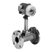
TRIO-WIRL VR4000
User Manuals: ABB TRIO-WIRL VR4000 Vortex Flowmeter
Manuals and User Guides for ABB TRIO-WIRL VR4000 Vortex Flowmeter. We have
1
ABB TRIO-WIRL VR4000 Vortex Flowmeter manual available for free PDF download: Instruction Manual
ABB TRIO-WIRL VR4000 Instruction Manual (83 pages)
Flowmeter
Brand:
ABB
| Category:
Measuring Instruments
| Size: 2.79 MB
Table of Contents
Table of Contents
3
Read First
8
CHAPTER 1 Introduction
10
Description
10
Features
11
Organization
11
CHAPTER 2 Swirlmeter (TRIO-WIRL S)
12
General
12
Measurement Principle
12
Liquid Flow Back Pressure
12
Figure 2-1 Measurement Principle, Trio-Wirl S
12
Figure 2-2 Operating Principle, Trio-Wirl S
12
Swirlmeter Model Number Breakdown
13
Installation
15
Inspection
15
Location & Mounting
15
Recommended Inlet & Outlet Sections
15
Control Valve Installation
16
Extreme Temperature Applications
16
Figure 2-3 Meter Piping Requirements
16
Figure 2-4 Recommended Flange Bolt Tightening Sequence
16
Figure 2-5 Control Valve Installation
16
Figure 2-6 Insulating the Pipeline
17
Figure 2-8 Ambient/Fluid Temperature Relationship
17
Temperature/Pressure Monitoring
18
Swirlmeter Size Selection
18
Gas
18
Figure 2-9 Measuring Pressure
18
Table 2-1. Swirl Flow Ranges, Air
18
Example for Gases
19
Pressure Drop, Gas & Steam
19
Table 2-2. Standard Densities for Selected Gases
19
Figure 2-10 Pressure Drop, Air
20
Liquid
21
Example for Liquids
21
Table 2-3. Swirl Flow Ranges, Liquid
21
Saturated Steam
22
Example for Saturated Steam
22
Figure 2-11 Pressure Drop, Water
22
Table 2-4. Swirl Flow Ranges, Saturated Steam
23
Specifications
24
Model Overview
24
Detailed Specifications
25
Figure 2-12 Ambient / Fluid Temperature Relationship
26
Figure 2-13 Process Pressure Vs. Process Fluid Temperature
26
CHAPTER 3 Vortex Meter (TRIO-WIRL V)
28
General
28
Measurement Principle
28
Figure 3-2 Strouhal Number / Reynolds Number Relationship
28
Vortex Model Number Breakdown
30
Installation
32
Inspection
32
Location & Mounting
32
Recommended Inlet & Outlet Sections
32
Figure 3-4 Meter Piping Requirements
33
Wafer-Style Installation
33
Figure 3-5 Wafer Process Connections, Sizes 1/2 through 2 Inches
34
Figure 3-6 Wafer Process Connections, Sizes 3 through 8 Inches
35
Figure 3-7 Wafer Style Assembly
35
Flanged-Style Installation
35
Control Valve Installation
36
Extreme Temperature Applications
36
Figure 3-10 Control Valve Installation
36
Figure 3-8 Recommended Flange Bolt Tightening Sequence
36
Figure 3-9 Flange Process Connections
36
Temperature/Pressure Monitoring
37
Figure 3-11 Insulating the Pipeline
37
Figure 3-13 Ambient/Fluid Temperature Relationship
37
Vortex Meter Size Selection
38
Gas
38
Table 3-1. Vortex Flow Ranges, Air
38
Table 3-2. Standard Densities for Selected Gases
38
Example for Gases
39
Flowrate Saturated Steam
39
Pressure Drop, Gas/Superheated Steam
39
Table 3-3. Minimum & Maximum Flowrates Vs. Density, Gases & Steam
39
Figure 3-14 Pressure Drop, Air
40
Table 3-4. Vortex Flow Ranges, Saturated Steam
40
Liquid
41
Pressure Drop, Liquid
41
Static Pressure, Liquid
41
Table 3-5. Vortex Flow Ranges, Water
41
Table 3-6. Minimum & Maximum Flowrates Vs. Viscosity, Liquid
41
Figure 3-15 Pressure Drop, Water
42
Specifications
43
Model Overview
43
Detailed Specifications
44
Figure 3-16 Ambient / Fluid Temperature Relationship
45
Figure 3-17 Process Pressure Vs. Process Fluid Temperature
45
CHAPTER 4 Converter
47
General
47
Figure 4-1 Integral Trio-Wirl Model Vt
47
Figure 4-2 Remote Trio-Wirl Model Vr
47
Figure 4-3 Vr/Sr Pipe-Mount Bracket
47
Converter Positioning
48
Data Entry
48
Figure 4-4 Converter Housing Rotation
48
ENTER Function for Magnetic Stick Operation
49
Figure 4-5 Converter Keypad & Display
49
Data Entry Overview
50
Operation and Configuration
51
Digital Communications Protocols
51
HART Protocol
51
Communication
51
Transmission Mode
51
Baudrate
52
Figure 4-6 Hart-Communication
52
Specifications
53
Overview
53
Detailed Specifications
54
Figure 4-7 Converter Keypad and Display
54
Figure 4-8 Outline Dimensions, Vr/Sr in Wall-Mount Housing
55
CHAPTER 5 Start-Up & Operation
56
Start-Up
56
Calibration Parameters
56
Firmware Version
56
Program Protection
56
Error Messages
56
Electrical Interconnections
56
TRIO-WIRL VT/ST4000 Integral
56
Figure 5-1 Instrument Data Tag
56
TRIO-WIRL VR/SR4000 Remote
57
Figure 5-2 Connection Box Trio-Wirl
57
Figure 5-3 Trio-Wirl Vr/Sr
57
Figure 5-4 Connection Box Trio-Wirl Vr/Sr Flowmeter Primary
57
Power Supply Interconnections
58
Figure 5-5 Interconnections between Converter and Flowmeter Primary
58
Figure 5-6 Central Power Supply
58
Figure 5-7 Transmitter Power Supply
58
Figure 5-8 Load Diagram
58
Hazardous Location Installation
58
Power Supplied from a Central Power Supply
58
Power Supplied from Transmitter Power Supply
58
Figure 5-9 Power Supply Interconnection Diagram, Hazardous Locations
59
Fm / Csa Label
59
Contact Output Connections
60
Converter Configuration
60
Additional Configuration Information
60
Data-Entry Check
60
Figure 5-11 Contact Output Connection
60
Meter Size
60
Calibration K-Factor
61
Current Output
61
Figure 5-13 Output Current Characteristics
61
Hardware Configuration
61
Normal Factor
62
Submenu Pulse Output
62
Configuring the Contact Output
63
TRIO-WIRL Menu Structure
64
Configuring Gases, Steam or Liquids
64
Trio-Wirl Menu Display and Selections
65
Changing the Displayed Language
65
Turning Locked Mode On/ off
66
Table 5-1. Top-Level Menu Structure
68
Top-Level Menu Structure
68
Complete Menu Structure Overview and Data Entry
69
Error Display
75
Submenu Error Register
75
Table 5-2. Error Code Listing
75
CHAPTER 6 Troubleshooting
76
CHAPTER 7 Parts List
77
Replacement Parts
77
Flowmeter/Signal Converter Parts
79
Table 7-1. Flowmeter/Signal Converter Parts List
79
Kits / Accessories
80
Table 7-2. Kits / Accessories
80
Table 7-4. Meter Mounting Kits, Vortex Wafer
81
Flange Gaskets
82
Table 7-5. Flange Gaskets
82
Advertisement
Advertisement
Related Products
ABB ACF-NT V0309
ABB VLMD P
ABB VLMD-R P
ABB VLM-D1
ABB VLM-D2
ABB VLMD-1-2
ABB VLMD-1-2-R
ABB TRIO-WIRL VT4000
ABB VSN730
ABB TRIO-WIRL ST4000
ABB Categories
Industrial Equipment
Controller
Measuring Instruments
Battery Charger
DC Drives
More ABB Manuals
Login
Sign In
OR
Sign in with Facebook
Sign in with Google
Upload manual
Upload from disk
Upload from URL