Advertisement
Quick Links
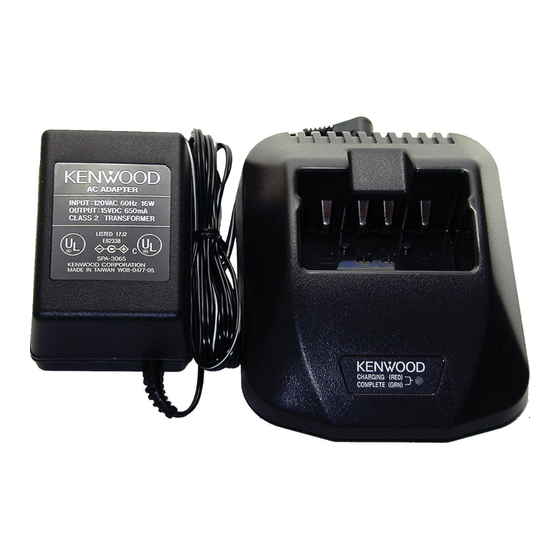
RAPID CHARGER
KSC-24
SERVICE MANUAL
AC adapter
(W08-0523-15) : K
(W08-0524-15) : E
(W08-0939-05) : T
Circuit Description
Power Supply Section
1. The power supply generates constant current (1.1A)
from the input voltage (rated 15V DC) from the adapter.
2. IC101 is a DC/DC converter.
3. R117 is a resistor for current detection.
4. R110 and R111 are resistors for no-load voltage detec-
tion (non-load voltage : 14V).
5. IC201 is a power supply/reset IC for the microcomputer
(IC202).
· Power output : 5V
· Reset output : "H" (Normal)
· After reset : "L"
Charging Control Section
1. The microcomputer (IC202) controls the following;
· Peak detection (Detected when fully charged, pin 27 of
IC202)
· Temperature control (Pin 2)
· Detection of abnormality, such as a short terminal (Pin
27)
· LED control (Red : Pin 21, Green : Pin 22)
· Trickle charging (Pin 18)
· Quick charging (Pin 17)
2. X201 is an oscillator that generates clocks for the micro-
computer (4MHz).
© 2001-5 PRINTED IN JAPAN
B51-8583-00 ( N ) 1775
Relay terminal
(E23-1058-08) x 4
Cabinet (Upper)
(A02-3626-08)
Charging Switch Section
1. Q201 is a transistor that turns quick charging on and off.
2. Q202 is a transistor that turns trickle charging on and off.
3. The resistor (R204) determines the leakage current.
Display Section
1. LED201 is a two-color LED that indicates the charging
state.
2. Red on ............... Quick charging or warming up
Green on ............ Charging is complete
Red blinking ....... Abnormal (short terminal, short bat-
tery, or open terminal)
Charging
The charging time for each pack is shown in the table.
Battery
Battery
Voltage
Pack
Type
(Volts)
KNB-14
Ni-Cd
7.2
KNB-15A
Ni-Cd
7.2
KNB-16A
Ni-Cd
7.2
KNB-17A
Ni-Cd
7.2
KNB-20N
Ni-MH
7.2
KNB-21N
Ni-MH
7.2
KNB-22N
Ni-MH
7.2
Photo is K type.
Battery
Approximate
Capacity
Charging Time
(mAh)
(Minutes)
600
40
1100
60
1100
60
1500
80
1600
80
1600
80
2100
110
Advertisement

Summary of Contents for Kenwood KSC-24
-
Page 1: Circuit Description
RAPID CHARGER KSC-24 SERVICE MANUAL © 2001-5 PRINTED IN JAPAN B51-8583-00 ( N ) 1775 AC adapter (W08-0523-15) : K Relay terminal (W08-0524-15) : E (E23-1058-08) x 4 (W08-0939-05) : T Cabinet (Upper) (A02-3626-08) Photo is K type. Circuit Description... -
Page 2: Parts List
KSC-24 PARTS LIST / EXPLODED VIEW / PC BOARD VIEW Parts List Exploded View : New parts Desti- Ref. No. Parts No. Description parts nation A02-3626-08 Cabinet (Upper) A02-3652-08 Cabinet (Lower) E03-0187-08 DC jack E23-1058-08 Relay terminal F09-0455-08 Thermal fuse... - Page 3 KSC-24 CIRCUIT DIAGRAM...
-
Page 4: Specifications
Mechelsesteenweg 418 B-1930 Zaventem, Belgium KENWOOD ELECTRONICS FRANCE S.A. 13, Boulevard Ney, 75018 Paris, France KENWOOD ELECTRONICS U.K. LIMITED KENWOOD House, Dwight Road, Watford, Herts., WD1 8EB United Kingdom KENWOOD ELECTRONICS EUROPE B.V. Amsterdamseweg 37, 1422 AC Uithoorn, The Netherlands KENWOOD ELECTRONICS ITALIA S.p.A.


