Table of Contents
Advertisement
Quick Links
AJY045LETDHS
INSTALLATION MANUAL
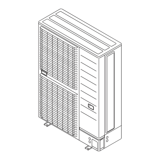
VRF SYSTEM OUTDOOR UNIT
For authorized service personnel only.
INSTALLATIONSANLEITUNG
VRF-SYSTEM AUSSENGERÄT
Nur für autorisiertes Fachpersonal.
MANUEL D'INSTALLATION
UNITÉ EXTÉRIEURE À SYSTÈME VRF
Uniquement réservé aux techniciens agréés.
MANUAL DE INSTALACIÓN
UNIDAD EXTERIOR DEL SISTEMA VRF
Sólo para personal de servicio autorizado.
MANUALE D'INSTALLAZIONE
UNITÀ ESTERNA DEL SISTEMA VRF
A uso esclusivo del personale tecnico autorizzato.
ΕΓΧΕΙΡΙΔΙΟ ΕΓΚΑΤΑΣΤΑΣΗΣ
ΕΞΩΤΕΡΙΚΉ ΜΟΝΆΔΑ ΣΥΣΤΉΜΑΤΟΣ VRF
Μόνο για εξουσιοδοτημένο τεχνικό προσωπικό.
MANUAL DE INSTALAÇÃO
UNIDADE EXTERIOR DE SISTEMA VRF
Apenas para técnicos de assistência autorizados.
РУКОВОДСТВО ПО УСТАНОВКЕ
СИСТЕМА VRF ВНЕШНЕГО МОДУЛЯ
Только для авторизованного обслуживающего персонала.
KURULUM KILAVUZU
VRF SİSTEMİ DIŞ ÜNİTESİ
Yalnızca yetkili servis personeli için.
PART No. 9380545521-01
Advertisement
Table of Contents

Related Manuals for Fujitsu AJY045LETDHS


Summary of Contents for Fujitsu AJY045LETDHS
- Page 1 UNITÉ EXTÉRIEURE À SYSTÈME VRF Uniquement réservé aux techniciens agréés. MANUAL DE INSTALACIÓN UNIDAD EXTERIOR DEL SISTEMA VRF Sólo para personal de servicio autorizado. AJY045LETDHS MANUALE D’INSTALLAZIONE UNITÀ ESTERNA DEL SISTEMA VRF A uso esclusivo del personale tecnico autorizzato. ΕΓΧΕΙΡΙΔΙΟ ΕΓΚΑΤΑΣΤΑΣΗΣ...
-
Page 2: Table Of Contents
INSTALLATION MANUAL [Original instructions] 1. SAFETY PRECAUTIONS VRF system outdoor unit • Be sure to read this installation manual thoroughly before installation. PART No. 9380545521-01 • The warnings and precautions indicated in this installation manual contain important information pertaining to your safety. Be sure to observe them. Contents •... -
Page 3: About This Product
This mark indicates procedures which, if improperly per- 2. ABOUT THIS PRODUCT CAUTION formed, might possibly result in personal harm to the user, or damage to property. 2.1. Precautions for using R410A refrigerant This unit must be installed by qualified personnel with a capacity certificate for handling refrigerant fluids. -
Page 4: Combinations
2.4. Combinations 3.2. Drain processing The number of indoor units that can be connected are as follows: CAUTION Connectable total Outdoor unit cooling Maximum connect- Model indoor unit capacity Perform drain work in accordance with this manual, and ensure that the drain water is capacity [kW] able indoor units ratio [%]... -
Page 5: Transporting The Unit
3.3.1 Single outdoor unit installation 3.3.3 Outdoor units installation in multi row * The following settings are not recommended in case of cooling by a low outdoor tem- When the upward area is open (Unit: mm) perature. (Unit: mm) (1) Obstacles at rear only (2) Obstacles at rear and sides only (1) Single parallel unit arrangement (2) Multiple parallel unit arrangement... -
Page 6: System Configuration
Table. C (Diameter of pipes used between separation tubes) 4. SYSTEM CONFIGURATION Total cooling Outside diameter [mm(in.)] Separation capacity of indoor Header (*4) 4.1. System configuration tube (*4) Liquid pipe Gas pipe unit [kW] x < 11.2 9.52 (3/8) 15.88 (5/8) UTR-H0906L CAUTION UTP-AX054A... -
Page 7: Opening The Knockout
Fig. B Fig. C PROHIBITED Header Horizontal line Horizontal line Gas pipe β = 0 to 10 mm (α : 0° to 1°) Slit Outdoor α β : -10° to 10° GOOD View Slit unit side Bottom Horizontal line Vertical line Liquid pipe connection = 0 to 10 mm... -
Page 8: Electrical Wiring
5.4.2 Bending pipes 6. ELECTRICAL WIRING CAUTION 6.1. The precautions of electrical wiring To prevent breaking of the pipe, avoid sharp bends. Bend the pipe with a radius of curvature of 100 mm or more. WARNING If the pipe is bent repeatedly at the same place, it will break. Wiring connections must be performed by a qualified person in accordance with speci- •... -
Page 9: Knockout
In case of connected outdoor unit 6.2. Knockout AJ*040/045/054LBLDH model Transmission cable 230 V ~ 50 Hz CAUTION Indoor unit Be careful not to deform or scratch the panel while opening the knockouts. Power supply cable After opening the knockouts, remove burr on the edges, and attach the one-touch bush 230 V ~ 50 Hz (accessory), grommet or conduit etc. -
Page 10: Wiring Method
Fig. 2 AJ*040/045/054LELDH model Power supply: 400V 3N~ 50 Hz NOTES: Breaker: NS 1 (3) Earth-leakage circuit breaker Do not use loop wiring. This Outdoor unit L1 L2 L3 may lead to parts damage and (4) Current breaker (over current) Indoor unit erroneous operation. -
Page 11: External Input And External Output
AJ*040/045/054LELDH model 6.6. External input and external output 6.6.1 Terminal position Transmission terminal (M3) Outdoor unit PC board Base pan heater Power supply terminal (CN115: Black) Cable tie (accessory) Cable clamp Ring terminal (M5) Input 4 (CN134: Red) Input 5 (CN135: Input 3 Orange) -
Page 12: Field Setting
6.6.2 External input terminal *5: Provide a DC 12 to 24 V power supply. Select a power supply capacity with an ample surplus for the connected load. Settings to low noise mode, cooling priority/heating priority selection, outdoor unit opera- *6: The allowable current is 30 mA or less. tion peak control setting, emergency/batch stop and electricity meter pulse are possible Provide a load resistance such that the current becomes 30 mA or less. -
Page 13: Rotary Switch Setting
Example of terminating resistor setting Priority given to the first command NS1 (Network segment 1) Terminal resistor Operation mode Priority given to external (Set terminal resistor at outdoor units) setting selecting method input of outdoor unit (*1) • Outdoor unit Terminal resistor: on Priority given to administra- : Set to on... -
Page 14: Address Setting For Signal Amplifiers
(1) Turn on the power of the outdoor unit and enter standby mode. 7.5. Address setting for signal amplifiers • When system is abnormal • When system is normal Check the settings as there is an error in the POWER/MODE lamp is on. 7.5.1 Address setting for signal amplifiers settings for outdoor unit address (ERROR lamp is off.) -
Page 15: Resistance Measurement Of Transmission Cable (Measure With Breaker Off)
7.6.2 Procedures to enable automatic address setting on indoor 8. PIPE INSTALLATION II units Check that the rotary switch IU AD on the indoor unit PC board is set to “00”.If it is not set Fig. A Connection system Fig. B to “00”, it means the address of that device is not set. -
Page 16: Additional Charging
Evacuation procedure (1) Calculation of additional amount for pipe length (1) Remove the blank caps of the gas pipe and liquid pipe and check that the valves are Total length of ø 9.52 Total length of ø 6.35 mm liquid pipe mm liquid pipe closed. -
Page 17: Test Run
9.1.3 Error displays 9. TEST RUN • When error occurs, “Err” and “Number of errors occurred” are alternately displayed on the 7-segment display every 1 second. 9.1. Indoor unit connection check • For the content of error, refer to “10.2. Error codes”. •... -
Page 18: Checklist
Test operation setting method 10. STATUS DISPLAY Use the “MODE/EXIT”, “SELECT”, and “ENTER” buttons on the indoor unit PC board to configure settings according to the procedures below. 10.1. Normal operation codes Function settings First 2 digits Last 2 digits Mode Code Description... -
Page 19: Information
Dry-bulb temperature and wet-bulb temperature (16) Condition of max. cooling at maximum electric current and input (17) Manufacture year Manufacture year (18) Origin Origin country Manufacturer FUJITSU GENERAL LIMITED (19) Manufacturer Address: 3-3-17, Suenaga, Takatsu-ku, Kawasaki 213-8502, Japan En-18...