Table of Contents
Advertisement
WELDER USER'S GUIDE
GUÍA PARA USAR LA SOLDADORA
GUIDE DE L 'UTILISATEUR DE LA
SOUDEUSE
Instructions on the use of your Wire Feed Welder
Instrucciones para el uso de su soldadora de carrete
Instruction d'utilisation de votre soudeuse à alimentation
en fil
Model 117-076
Made
in
U.S.A.
©
Form No. 811-592-002 Rev. A
December 2000
117-076, 2145, 83125, 83126, 20511, 125 GL, 125GS
1
Advertisement
Table of Contents

Summary of Contents for Craftsman 117-076
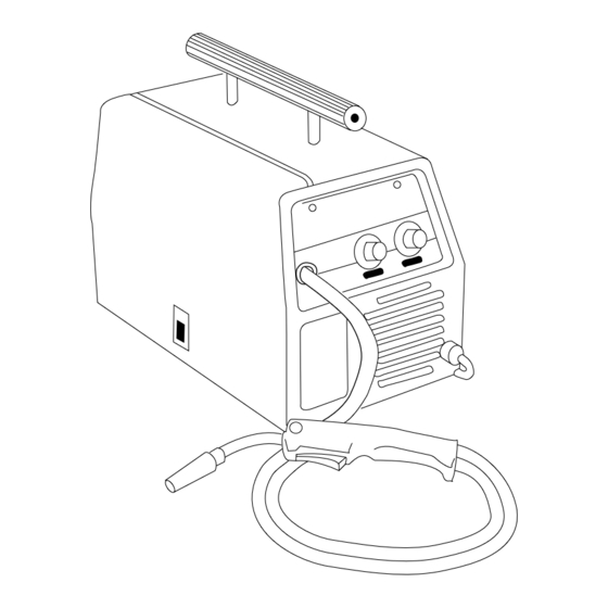
- Page 1 Instructions on the use of your Wire Feed Welder Instrucciones para el uso de su soldadora de carrete Instruction d’utilisation de votre soudeuse à alimentation en fil Model 117-076 Made U.S.A. © Form No. 811-592-002 Rev. A December 2000 117-076, 2145, 83125, 83126, 20511, 125 GL, 125GS...
-
Page 2: Table Of Contents
TABLE OF CONTENTS ENGLISH INTRODUCTION ........................5 SAFETY SUMMARY ......................5 SAFETY INFORMATION ....................... 5 SHOCK HAZARDS ........................5 FIRE HAZARDS ......................... 5 FLASH HAZARDS ........................6 FUME HAZARDS ........................6 COMPRESSED GASSES AND EQUIPMENT HAZARDS ............6 BURN HAZARDS ........................6 ADDITIONAL SAFETY INFORMATION .................. -
Page 3: Introduction
SAFETY SUMMARY Every craftsman respects the tools with which they work. They This symbol indicates that the eye protection should know that the tools represent years of constantly improved be worn to protect against flying debris in the designs and developments. -
Page 4: Flash Hazards
understands and follows these safety instructions as well. ADDITIONAL SAFETY INFORMATION REMEMBER! Welding by nature produces sparks, hot For additional information concerning welding safety, refer to the spatter, molten metal drops, hot slag, and hot metal parts following standards and comply with them as applicable. that can start fires, burn skin, and damage eyes. -
Page 5: Welder Operating Characteristics
recommended that a qualified electrician verify the ACTUAL Optional on some welder models VOLTAGE at the receptacle into which the welder will be plugged and confirm that the receptacle is properly fused and MIG welders equipped with gas are capable of welding with grounded. -
Page 6: Install The Shielding Gas
IMPORTANT – GAS CYLINDER SIZE RESTRICTION! The INSTALL THE SHIELDING GAS tank tray you have just installed on the back of the welder will handle gas cylinders no larger than 20 cubic feet. If you select a cylinder larger than 20 cubic feet, it must be chained to a wall WARNING or other fixed support. -
Page 7: Check The Gas Flow
4. Insert the gas hose into the outlet port of the gas regulator. 3. Loosen the drive roller setscrew and pull the drive roller off The hose locks in place in the fitting when pressed into the the drive shaft. port. -
Page 8: Install The Welding Wire
Liner Screws Right Way Inlet Drive Roller Guide Neoprene Drive Roller Tube Setscrew Motor Shaft Motor Shaft Flat Figure 5. Drive Assembly & Neoprene Drive Roller 6. Tighten the setscrew, while holding the drive roller in place. Wrong Way 7. Remove the screws that retain the inlet guide tube. Replace the plastic inlet guide tube with the supplied brass inlet guide tube. -
Page 9: Set The Wire Drive Tension
SET THE WIRE DRIVE TENSION Note: If TOO MUCH tension is applied to the wire spool, the wire will slip on the drive roller or will not be able to feed at all. If TOO LITTLE tension is applied, the spool of wire will want to unspool itself. -
Page 10: Operation
3. Start the four nuts on the four connecting posts and hand snug each nut with the 7/16 nut driver. Do not use a ratchet, crescent or other lever type wrench. WARNING OPERATION ELECTRIC SHOCK CAN KILL! To reduce the risk of Operation of this welder consists of selecting and adjusting electric shock, always unplug the welder from its ac power source before removing side panels. -
Page 11: Maintaining The Contact Tip
Tools Required: 15. Insert the head of the gun liner through the internal star lock washer and the live wire terminal (repeat the • 5/16 inch open end wrench orientation noted in step 9). With a 5/16 inch open end •... -
Page 12: Testing For A Shorted Nozzle
Failure to keep the nozzle adequately cleaned can result in the contact tip and the outside of the nozzle. If there is any following problems: continuity at all, the nozzle IS shorted. Clean or replace as needed. A SHORTED nozzle results when spatter buildup bridges the PREVENTIVE MAINTENANCE insulation in the nozzle allowing welding current to flow through it as well as the contact tip. -
Page 13: Schematic Diagram
SCHEMATIC DIAGRAM... -
Page 14: Wiring Diagram
WIRING DIAGRAM... -
Page 15: Manufacturer's Limited Warranty
MANUFACTURER’S LIMITED WARRANTY The manufacturer warrants that it will repair, at no charge for parts or labor, the Welder or Welding Gun or Cables, proven defective in material or workmanship, during the following time period(s) after date of original retail purchase: For 5 Years: The Welders Transformer and Rectifier For 2 Years: The Entire Welder (excluding accessories packed with the welder) For 1 Year:...


