Advertisement
Quick Links
SPECIFICATIONS
CONTENTS
Great user manuals database on
Cordless Wood Saw / Cordless Metal Cutter
Page
2
2
3
UserManuals.info
EY3551-U1
EY3552-U1
© 2005 Matsushita Electric Works Ltd. All rights
reserved. Unauthorized copying and distribution is a
violation of law.
ORDER NO.PTD0501U30C1
F16
Page
7
12
14
Advertisement

Summary of Contents for Panasonic EY3551
-
Page 1: Table Of Contents
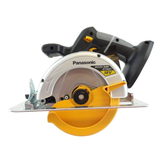
ORDER NO.PTD0501U30C1 Cordless Wood Saw / Cordless Metal Cutter EY3551-U1 EY3552-U1 SPECIFICATIONS CONTENTS Page Page 1 SCHEMATIC DIAGRAM 4 ASSEMBLY INSTRUCTIONS 2 WIRING CONNECTION DIAGRAM 5 TROUBLESHOOTING GUIDE 3 DISASSEMBLY INSTRUCTIONS 6 EXPLODED VIEW & REPLACEMENT PARTS LIST © 2005 Matsushita Electric Works Ltd. All rights reserved. -
Page 2: Schematic Diagram
EY3551-U1 / EY3552-U1 1 SCHEMATIC DIAGRAM 2 WIRING CONNECTION DIAGRAM <EY3551> <EY3552> Great user manuals database on UserManuals.info... -
Page 3: Disassembly Instructions
EY3551-U1 / EY3552-U1 3 DISASSEMBLY INSTRUCTIONS IBLADE REMOVAL. Ref. No. 1A Procedure 1A Blade removal. NOTE : Make sure that the battery pack is removed from the saw prior to servicing. The blade will be hot right after cutting. Be sure to let the blade cool down before removing it. - Page 4 EY3551-U1 / EY3552-U1 IMAIN UNIT DISASSEMBLY. (The main unit can be opened without removing the shoe.) Ref. No. 2A Procedure 2A Removal of the safety cover and lower guard. 1. Loosen the base depth adjustment lever where located under the grip of main unit and push the shoe down.
- Page 5 EY3551-U1 / EY3552-U1 Procedure 2A → → → → 2B Ref. No. 2B Removal of the shoe. NOTE: It is possible to disassemble the main unit without removing the shoe. 1. Take out the E-ring and the depth adjustment lever.
- Page 6 EY3551-U1 / EY3552-U1 Procedure 2A → → → → 2C → → → → 2D Ref. No. 2D Removal of the gear box block. 1. Loosen the 4 screws where securing the driving block with the housing in order to take out the gear box block from the main unit.
-
Page 7: Assembly Instructions
EY3551-U1 / EY3552-U1 4 ASSEMBLY INSTRUCTIONS CAUTION: The proper operation of the “off lock lever” is critical for the safe use and operation of the saw/cutter. Be extra careful in re- assembling the unit and ensure that the “off lock lever” is properly positioned. Verify the operation of the “off lock lever” upon completing the re-assembly procedure. - Page 8 EY3551-U1 / EY3552-U1 Procedure 3A → → → → 3B Ref. No. 3B Assembly of the spindle lock button and gear box. 1. Push and hold the spindle lock button while inserting the gearbox block. NOTE: Confirm the direction of the spindle lock button. Place D-cut on top.
- Page 9 EY3551-U1 / EY3552-U1 Procedure 3A → → → → 3B → → → → 3C → → → → 3D Ref. No. 3D Assembly of the off lock lever. 1. Put the off lock lever into the housing boss. 2. Insert the one side of lever spring into the groove of the off lock lever.
- Page 10 EY3551-U1 / EY3552-U1 Ref. No. 3F Procedure 3A → → → → 3B → → → → 3C → → → → 3D → → → → 3E → → → → 3F Assembly of the shoe. 1. Insert the spring pin with a rod having a diameter of 5mm.
- Page 11 EY3551-U1 / EY3552-U1 Ref. No. 3G Procedure 3A → → → → 3B → → → → 3C → → → → 3D → → → → 3E → → → → 3F Assembly of the blade guard assembly. → → → → 3G 1.
-
Page 12: Troubleshooting Guide
EY3551-U1 / EY3552-U1 5 TROUBLESHOOTING GUIDE (Refer to WIRING CONNECTION DIAGRAM) Great user manuals database on UserManuals.info... - Page 13 EY3551-U1 / EY3552-U1 Great user manuals database on UserManuals.info...
-
Page 14: Exploded View & Replacement Parts List
EY3551-U1 / EY3552-U1 6 EXPLODED VIEW & REPLACEMENT PARTS LIST 6.1. EXPLODED VIEW for EY3551 Great user manuals database on UserManuals.info... - Page 15 EY3551-U1 / EY3552-U1 6.2. REPLACEMENT PARTS LIST for EY3551 NOTE: *B=only available as set *C=available individually Ref.No. Part No. Part Name & Description Remarks Per Unit EY3500K0357 SPRING PIN 6-45 WEY3551S3428 BASE EY3503K6487 ADJUSTING BOLT M5*10 EY3503K0197 SPRING 7.6*15 WEY3552S6388...
- Page 16 EY3551-U1 / EY3552-U1 6.3. EXPLODED VIEW for EY3552 Great user manuals database on UserManuals.info...
- Page 17 EY3551-U1 / EY3552-U1 6.4. REPLACEMENT PARTS LIST for EY3552 NOTE: *B=only available as set *C=available individually Ref.No. Part No. Part Name & Description Remarks Per Unit EY3500K0357 SPRING PIN 6-45 WEY3552S3428 BASE EY3503K6487 ADJUSTING BOLT M5*10 EY3503K0197 SPRING 7.6*15 WEY3552S6258...


