Table of Contents
Advertisement
Quick Links
ISO 9001
Use, features
General features
Specific features
CC1N7138en
22.07.2002
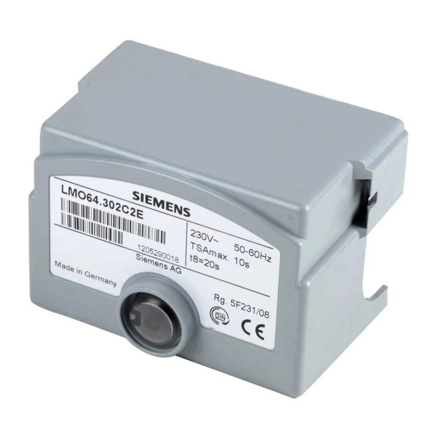
Oil Burner Controls
Microcontroller-based oil burner controls for the supervision, startup and control
of forced draft oil burners in intermittent operation. Oil throughput up to 30 kg / h.
The LMO64... and this Data Sheet are intended for use by OEMs which integrate
the burner controls in their products.
The LMO64... burner controls are designed for the startup and supervision of single- or
2-stage forced draft oil burners in intermittent operation. Yellow-burning flames are
supervised with photoresistive detectors QRB..., blue-burning flames with blue-flame
detectors QRC... .
Forced draft oil burners conforming to EN 267
-
Burner controls for use with atomization burners of monoblock design conforming to
-
EN 230
Undervoltage detection
-
Electrical remote reset
-
Bridging contact for oil preheater
-
Monitoring of time for oil preheater
-
Accurate and reproducible program sequence through digital signal handling
-
Controlled intermittent operation after 24 hours of continuous operation
-
Limitation of the number of repetitions
-
Multicolor indication of fault and status messages
-
Postpurge function for clearing the combustion chamber after burner operation
-
Siemens Building Technologies
HVAC Products
7
138
LMO64...
Advertisement
Table of Contents

Summary of Contents for Siemens LMO64 Series
- Page 1 Controlled intermittent operation after 24 hours of continuous operation Limitation of the number of repetitions Multicolor indication of fault and status messages Postpurge function for clearing the combustion chamber after burner operation Specific features Siemens Building Technologies CC1N7138en HVAC Products 22.07.2002...
-
Page 2: Installation Notes
Never run the detector cable together with other cables – Line capacitance reduces the magnitude of the flame signal – Use a separate cable · Note the maximum permissible detector cable lengths (refer to «Technical data») 2/10 Siemens Building Technologies CC1N7138en HVAC Products 22.07.2002... -
Page 3: Commissioning Notes
Multicolor display of status and fault messages Display and diagnosis Transmission of status and fault messages as well as detailed service information by additional interface adapter OCI400 and PC Windows software ACS400. 3/10 Siemens Building Technologies CC1N7138en HVAC Products 22.07.2002... -
Page 4: Type Summary
Flame detectors Photoresistive detectors QRB1... refer to Data Sheet 7714 Blue-flame detectors QRC1... refer to Data Sheet 7716 Diagnostic tool refer to Data Sheet 7614 Interface adapter OCI400 PC Windows software ACS400 4/10 Siemens Building Technologies CC1N7138en HVAC Products 22.07.2002... -
Page 5: Technical Data
Blue Black Brown QRB... QRC1... As an alternative to detector current measurement, the diagnostic tool OCI400 / ACS400 can be used. In that case, connection of the DC microammeter is not required. 5/10 Siemens Building Technologies CC1N7138en HVAC Products 22.07.2002... - Page 6 The red signal lamp will flash. If the flame is lost for the fourth time during operation, the burner will initiate lockout. The repetition count is restarted each time controlled switching on by «R-W-SB» takes place. 6/10 Siemens Building Technologies CC1N7138en HVAC Products 22.07.2002...
- Page 7 Red flashing .......... Output of fault code (refer to «Error Red flicker light code table») = = = = = = = Interface diagnosis Red flicker light ..Permanent Legend Yellow Green 7/10 Siemens Building Technologies CC1N7138en HVAC Products 22.07.2002...
-
Page 8: Blink Code
The diagnosis of the cause of fault is quit and the burner switched on again by resetting the burner control. Press lockout reset button for about 1 second (< 3 seconds). 8/10 Siemens Building Technologies CC1N7138en HVAC Products 22.07.2002... -
Page 9: Control Sequence
Beginning of startup sequence with burners using no Controlled shutdown by «R» oil preheater Time of flame establishment End of startup sequence Control signals µC1 Microcontroller 1 Required input signals µC2 Microcontroller 2 Permissible input signals 9/10 Siemens Building Technologies CC1N7138en HVAC Products 22.07.2002... - Page 10 Dimensions Dimensions in mm LMO64... 41,64 88,5 LMO64.300B2 Color of plastic: Silver-grey (RAL7001) ã2002 Siemens Building Technologies AG Subject to change 10/10 Siemens Building Technologies CC1N7138en HVAC Products 22.07.2002...


